
A five-axis machined impeller is the only part in this section where the manufacturing process is not a service applied to the geometry but the thing that makes the geometry possible at all. Every other impeller – a die-cast one, a welded one, a hand-formed one – is made by a process that can produce curved surfaces because the process itself is three-dimensional. A machined impeller has to produce them by removing material with a tool that only moves in straight lines, which means the machine has to move in five axes at once and reposition continuously while it does it.
And the surface that comes out of that is the product. Not the tip diameter, not the bore, not the balance – the blade surface itself, and specifically whether it is smooth and continuous and free of steps.
The blade surface is the specification
A blade’s shape determines what the impeller does. Its camber determines the pressure it produces, its thickness distribution determines how much it deforms under load, and its surface determines how much friction there is. The performance-critical property is not the blade’s outline – it is the blade’s surface, and specifically the tool path’s continuity.
On a three-axis machine, a curved blade surface is machined as a series of stepped passes. The step height is the Z-resolution, typically a few hundredths of a millimetre, and between passes the tool has to reposition. Where it repositions – at the end of one pass and the start of the next – it leaves either a ridge or a scallop, and the surface has a periodic discontinuity in it. The consequence:
- On a casting or a formed blade, the surface is smooth and continuous because the process produced it continuously.
- On a three-axis machined blade, the surface is stepped. For a coarse application – a slow-moving fluid, a large impeller, a low efficiency requirement – the steps are negligible and nobody notices.
- On a five-axis machined blade, the tool can stay engaged and move through the whole blade in one continuous path, so the surface is smooth. This is the actual reason five axes is used on this part, and it is worth being clear that it is a surface-quality and performance reason, not an accuracy reason. A five-axis machine is not more accurate than a good three-axis machine. It is able to produce a continuous surface.
So the practical question on an impeller’s specification is: how smooth does the blade have to be, and for what performance? A pump moving clean water does not need a polished blade. A compressor stage, a fuel pump, or anything where efficiency and cavitation margin matter does. That question sets whether three axes with a ball end mill is adequate or whether continuous five-axis pathing is required, and the two are very different in cost.
Cavitation, and the surface finish requirement that follows
Wherever a blade’s pressure falls below the fluid’s vapour pressure, cavitation bubbles form and then collapse. Three consequences that make the surface matter:
- Cavitation inception is affected by surface roughness. Nucleation sites on a rough surface are the roughness’s peaks, so a rougher blade initiates cavitation at a lower pressure than a smooth one. The blade’s roughness is therefore a performance specification, not a cosmetic one.
- Cavitation damage is progressive and it is cumulative. Each collapse of a bubble produces a small impact that pits the surface, and the pits become the nucleation sites for the next generation. A blade that starts slightly rough degrades faster than one that started smooth, so the initial finish compounds.
- The damage mechanism is different from simple erosion. Cavitation is often described as pitting, and it produces a distinctive grey, porous appearance rather than the smooth scallops of erosion. Where a blade has been cavitating, the damage is generally not repairable – the material has been removed and work-hardened around it.
So the honest specification on a performance impeller is a surface finish on the blade’s working surface, stated with a convention, plus a statement of what the fluid is. “Ra 0.8” on a drawing for a blade means something quite different for a water pump and for a hydrocarbon pump, and it should be tied to a stated measurement standard.
Balance, which is a different discipline again
On a machined impeller, balance is arguably easier than on a cast one – there is no casting variation and the material is homogeneous – but it is more sensitive, because a machined blade’s mass distribution is entirely a consequence of the machining and any asymmetry is entirely your fault.
- Mass, not just shape. A balanced impeller is one where the centre of mass sits on the rotation axis and where the mass moment of inertia is balanced about it. A cast impeller’s flow passages vary slightly, so the as-cast part needs correcting. A machined impeller is nominally symmetric by design, which means the balance quality comes from the machining’s accuracy rather than from a correction step.
- Runout is not the same as balance. Runout is a geometric measurement of the rotation relative to a datum. Balance is a mass property. An impeller can have excellent runout and be badly out of balance, and it can have modest runout and be well balanced. For an impeller, balance is what matters; runout matters for the part’s fit and its tip clearance.
- Tip clearance and its effect on balance in service. Once an impeller is running, deposits and wear change its mass distribution. An impeller that was balanced at the factory will drift. On a high-speed or close-tolerance application this is a known life issue, and it argues for a material and a surface treatment that resist deposit – which is one of the practical arguments for a machined and finished blade over an as-cast one.
- The balance grade should be specified rather than assumed, and for a part running at high tip speed the required grade is a genuine design parameter.
Cavitation resistance makes an impeller’s alloy consequential
1050, 3003, 5052 and 6061 aluminium at 0.5 to 3.0 mm stock, with temper matched to the route. On an impeller the alloy and temper are more consequential than on most parts, for three reasons.
- Cavitation damage resistance is a material property. Aluminium alloys vary significantly in their resistance to cavitation erosion, and the harder alloys generally resist it better. A part designed for a cavitating service should have the alloy chosen for that and not for machinability.
- A blade’s deflection under load changes its performance. A blade that deflects under the pressure it is generating is a blade with a different camber in operation than on the bench. The modulus of the material is therefore a performance variable, and this is the argument for a stiffer alloy in a high-pressure application.
- Corrosion on an aluminium impeller is a deposit mechanism. Aluminium’s oxide is protective but it is also the substrate for deposit, and a corroding blade in a water service will pick up scale and lose balance. So the alloy’s corrosion behaviour in the actual fluid is a balance question as much as a durability one.
For the decorative or lightly loaded cases – a fan, a low-pressure blower – 1050 and 3003 are perfectly adequate and they machine best. For anything with a pressure ratio to achieve, 5052 and 6061 are the realistic choices, and the temper matters: a T6 condition gives the strength and stiffness but costs machinability, which on a five-axis job is a real cost because the tool life is the constraint.
Five axes specifically, and what it buys
Worth stating plainly, because “5-axis” is often used as a marketing word rather than an engineering one.
- What it buys: the ability to complete the part in one clamping with the blade accessible, which means the blade’s relationship to every other feature – the bore, the hub, the back shroud, the tip diameter – is set by the machine’s kinematics rather than by a fixture. And it means a continuous tool path over the blade.
- What it does not buy: accuracy for its own sake. The positional accuracy of a good 5-axis machine is comparable to a good 3-axis machine. The advantage is in the geometry that can be reached and in the setups that are avoided.
- When it is worth paying for: when the geometry genuinely requires it. A blade on a face that is at an angle to every machine axis; a part that would otherwise need three or four setups and therefore three or four fixture errors; a blade that needs a continuous path. When the part is a simple hub with a flat blade, a 3-axis machine with a fourth axis will produce an equally functional impeller at a lower cost.
- The real costs of 5-axis: programming time and the skill to do it well, simulation before cutting because a crash on a five-axis program is expensive, tool life management because the tool is working at varying angles and therefore varying cutting conditions, and inspection – a five-axis part’s features are not all in a convenient orientation for a CMM probe, so the inspection plan has to be designed rather than assumed.
One more practical point: the part’s stock size drives a five-axis job as much as the geometry does. A five-axis machine works well with a near-net-shape blank rather than a solid block, because the machine’s time is spent on the features rather than on removing air. At 0.5 to 3.0 mm stock here, the blanks are thin, which is a different regime again – a thin impeller blank is much easier to machine but it deforms on the machine, and a fixturing plan that ignores that will produce blades that are not in the same plane.
Blade thickness distribution matters more than the impeller’s outside diameter
+/-0.02 mm general machining, tighter on flagged dimensions, GD&T per drawing, PPAP-style reports on request. On an impeller the flagged dimensions are specific and they are almost all about the blade.
- Blade thickness, at its thickest and thinnest points, since the thickness distribution is what determines how the blade deforms under load. This is a profile requirement, not a point measurement.
- Blade angle and camber, which together are the blade’s aerodynamic or hydraulic geometry. On a machined blade these are held by the machine’s kinematics and they are verifiable on the CMM by probing the blade’s surface.
- Surface finish on the blade’s working surface, as discussed, and it is worth noting this is one of the few places where a general surface note is inadequate.
- Tip diameter and the tip clearance to the housing, because tip clearance directly affects leakage past the impeller and therefore efficiency.
- Blade-to-blade variation in the radial and axial positions, which is what makes the impeller balanced. Holding each blade’s position to its neighbours is a different requirement from holding each blade to the part datum, and the second is the one that matters for balance.
- Runout of the blade surfaces relative to the bore, because a blade that is 0.1 mm out of plane at its tip will be running with a clearance that varies around the rotation.
- General dimensions at the general band, and the hub’s bore and its mounting face held to their own requirements.
With PPAP-style reports available, this is a part where that documentation is worth asking for. An impeller is a rotating component whose failure mode is a balance change, and a documented first article with blade geometry, balance grade and surface finish recorded is the only way to answer a question after a failure.
Coating an impeller blade changes its mass and its balance
Natural, plated or coated per the print, with the agreed finish travelling with the part number. On an impeller the finish question is narrow and important: do not coat the blade surfaces unless there is a specific reason. A coating on a blade changes its mass, and even a nominally uniform coating on a blade whose thickness distribution is not symmetric will unbalance the impeller. Where a coating is specified on an impeller – a corrosion-resistant coating on an aluminium blade in a marine service, for example – it should be applied before the balance operation and the balance measured after coating.
Inspection on this part, in the order it should be done:
- Balance, measured and recorded, on every part. This is the requirement, not a nice-to-have.
- Blade geometry – thickness, angle, camber – probed and reported per blade rather than as an average.
- Blade surface finish, on the working surface.
- Tip diameter and tip clearance, with the runout of the blade relative to the bore.
- Runout, reported as a measured value against the print, and distinguished from balance in the report so the two are not confused later.
- A dimensional report on the flagged dimensions, with the balance grade and the surface finish recorded alongside it, so the part’s performance-critical characteristics travel with the part.
The fluid, and the cavitation margin
What is the fluid, and what is the cavitation margin? Because that single question decides whether the blade needs a machined-and-finished surface at all. In a clean, low-pressure water application with plenty of margin, an as-cast or as-formed aluminium blade is entirely adequate, the surface requirement is nominal, and a three-axis machine with a fourth axis can produce a functional impeller. In a hydrocarbon, a refrigerant, or a high-pressure application, or in any service where cavitation is expected to occur, the blade’s surface finish and its material become the design, and continuous five-axis machining with a specified finish and a specified balance grade is what the part actually requires. It is also the difference between a part that costs what a machined impeller costs and one that costs a fraction of it. Establishing the fluid and the pressure at enquiry stage – two numbers – determines which of those parts is being quoted, and it costs one line on the enquiry form.
The CNC Machining Parts range is the parent for parts like this one; tooling logic, finishing options and tolerance notes for the whole family are gathered on its overview page.
Specifications
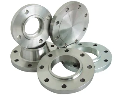
| Item | CNC Machined Flat Flange Rings with Bolt Holes |
|---|---|
| Brand | AUNOV |
| Designing | Your 2D/3D files (PDF, DWG, STEP, IGS) are reviewed for manufacturability before any price is confirmed. |
| Tooling | Dies, fixtures and gauges are made in our own toolroom, so a die can be re-cut against the approved drawing, and the die remains dedicated to your part. |
| Samples | The sample you approve becomes the gauge reference for production. |
| Materials | 1050 / 3003 / 5052 / 6061 aluminium, 0.5-3.0 mm stock – temper matched to the forming depth or machining route of this housing. |
| Surface finish | Natural, plated or coated – the print decides, and the agreed finish is logged; the agreed finish travels with the part number. |
| Processing | CNC turning with milling and drilling in as few setups as the geometry allows; batch records are filed so a repeat order starts from approved data. |
| Equipment | 12 CNC turning centres with automatic bar feeders, with in-house toolmaking to keep dies and fixtures maintained. |
| Tolerance | +/-0.02 mm general machining, tighter on flagged dimensions; GD&T per drawing, PPAP-style reports on request. |
| Delivery terms | CIF or DDP, with FOB available, T/T or L/C, with D/P accepted on repeat business; sea or air freight is quoted to your door. |
Related Products


Request a Quote for This Part
Send a drawing or sketch — get material advice, tooling cost and a per-piece price within 24 hours (working days).