
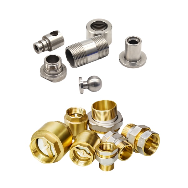
Barb profile geometry is what controls the seal, not just the OD
A hose barb fitting lives or dies by the shape of its barbs, not by the nominal outer diameter printed on the drawing. When the barb major diameter is on the low side of tolerance but each barb has a sharp leading edge, a correctly assembled clamp will still produce a reliable seal. The opposite case—a barb at the high end of the OD band with rounded or flattened crests—will weep under pressure regardless of how tightly the clamp is torqued. This distinction matters because most incoming inspection checks only the major diameter with a snap gauge or caliper and signs off. The actual seal interface is determined by the crest radius, the included angle of the barb taper, and the surface finish at those peaks.
On brass barbs produced from hex stock on a Swiss-type lathe, the crest radius is a direct function of insert wear. A fresh carbide insert ground to 0.05 mm nose radius will hold that value for roughly 2,000 parts in C360 brass before edge build-up begins to round it toward 0.08–0.10 mm. The process does not stop; the operator sees no dimensional alarm because the major diameter is still within spec. What changes is the contact pattern between the barb crest and the hose inner wall—instead of line contact along a sharp ridge, you get area contact against a blunt profile that cannot cut into the hose material enough to lock it in place under thermal cycling.
Why brass-to-steel transitions crack at the braze joint unless you control CTE mismatch
Many barb fittings are not monolithic brass. They combine a brass barb body with a steel threaded shank, joined by brazing or silver soldering. The coefficient of thermal expansion difference between brass (roughly 19 µm/m·K) and carbon steel (about 12 µm/m·K) means that every 50 °C temperature swing during operation or sterilization creates a differential strain of about 0.35 % across a typical 15 mm joint length. That does not sound like much until you realize that the braze filler metal—often a BAg-8 alloy with yield strength around 150 MPa—is carrying this strain as cyclic shear at the fillet root.
The failure mode is not immediate separation. It is fatigue cracking that initiates at the edge of the braze fillet where stress concentration is highest, then propagates through the filler until the joint weeps. We have seen fittings pass a room-temperature hydrostatic test at 1.5× working pressure and fail after 200 thermal cycles between –20 °C and +120 °C. The fix is not simply to use a higher-strength filler—that raises the stiffness mismatch and can make the problem worse. The practical countermeasure is to design the joint so that the braze overlap length is at least 1.5× the steel shank diameter, and to specify a post-braze stress-relief anneal at 450 °C for 30 minutes if the service temperature will exceed 80 °C.
Thread engagement depth on the shank determines whether the fitting backs out under vibration
The threaded end of a hose barb fitting is almost always the failure point in vibrating equipment—not the barb-to-hose interface. When a 1/4 NPT or M12 shank is installed into a cast aluminum manifold using a flat washer and nut, the axial preload from tightening is partially lost within the first hour of operation as micro-slip between the thread flanks works the nut loose. The rate of loosening is controlled by three variables: the thread pitch (coarse threads back out faster than fine), the initial preload relative to the yield threshold, and the presence or absence of a locking feature.
We specify a minimum full-thread engagement of 1.5D for steel-into-steel connections and 2.0D for steel-into-aluminum, where D is the nominal major diameter. Below these thresholds, the effective load-carrying thread count drops below three, and the joint behaves like a cantilever rather than a clamped column. On fittings where the customer drawing calls out only “standard thread depth” without a numeric value, we default to 1.75D and note it on the first-article report. If the application involves reciprocating compressors or engine-mounted pumps, we add a nylon patch or deformed-thread locking feature and verify retention torque after MIL-STD-810G random-vibration testing at 0.04 g²/Hz from 20–500 Hz.
Bore concentricity relative to the thread axis affects flow balance in multi-barb manifolds
On fittings with a through-bore that must align with an internal passage in a manifold—the common case for distribution blocks and header assemblies—the eccentricity between the bore centerline and the thread axis creates a step restriction at the entry plane. A 0.15 mm eccentricity on a 6 mm bore fitting installed into a 6.1 mm drilled passage produces an effective flow area reduction of about 8 % compared to the perfectly concentric case, because the minimum clearance occurs on one side while the opposite side opens up but does not compensate linearly.
This is not a concern for low-pressure coolant lines where the pump head absorbs the minor loss. It becomes critical when the same fitting design is used on fuel-rail branches or hydraulic distributor blocks where branch-to-branch flow uniformity is specified within ±5 %. In those cases, we hold bore-to-thread concentricity to 0.05 mm TIR and inspect every piece on a coordinate measuring machine, not just SPC sample batches. The added cost per part is about 0.8 minutes of CMM time, which is far cheaper than field-replacing a fuel rail that fails an OEM flow-matching test.
Surface finish inside the bore traps particulates when Ra exceeds 1.6 µm
The internal bore surface finish of a barb fitting is rarely called out on customer drawings, yet it directly determines how quickly the fitting becomes a contamination source in clean systems. A bore finished with a standard HSS drill bit leaving 3.2 µm Ra will retain machining debris and flux residue in its microscopic valleys even after aqueous cleaning. When pressurized fluid flows through, shear forces gradually dislodge this trapped material and carry it downstream—into servo valves, into injector nozzles, into particle counters that flag the system as out of spec.
We apply an internal reaming or honing pass to any fitting whose bore will see fluid velocity above 2 m/s or whose system has a cleanliness code stricter than ISO 18/16/13. The target is 0.8 µm Ra or better, with a unidirectional lay aligned to the flow direction. For small bores below 4 mm where honing tools are impractical, we use a pull-through ball burnishing operation that both sizes the bore and work-hardens the surface, reducing the Ra from the as-drilled 3–4 µm down to 0.6–1.0 µm in a single stroke without generating new chips.
How we verify that a batch of barb fittings will actually seal before it ships
Our final inspection for barb fittings combines dimensional checks with a functional seal test that mimics the actual assembly condition. Each fitting is fitted with a master hose segment (the specific SAE J1503 type specified for the part) and a constant-torque clamp set to the midpoint of the recommended range. The assembly is then pressurized to 1.5× the rated working pressure for 60 seconds while immersed in a water tank. Any bubble stream larger than one bubble every 5 seconds is grounds for rejection of that individual piece, not just the batch.
In addition to the pressure hold, we pull a destructive sample from each shift’s production (one piece per 200 units) and section it longitudinally to measure the actual barb embedment depth into the hose material. The target is 15–25 % of the hose wall thickness for SAE 20R3 Type A rubber and 10–18 % for the stiffer SAE 20R3 Type D. Embedment below the lower bound correlates with push-off failures in cold-temperature drop tests; above the upper bound risks cutting the reinforcement layer and causing hose burst failures at pressures below rating. This dual verification—pressure hold plus metallographic embedment check—is what separates a fitting that passes inspection from one that stays sealed in service.
The CNC Machining Parts range is the parent for parts like this one; tooling logic, finishing options and tolerance notes for the whole family are gathered on its overview page.
Specifications
| Item | Brass and Steel CNC Machined Hose Barb Fittings |
|---|---|
| Brand | AUNOV |
| Designing | A drawing file or a physical sample starts the review, DFM feedback is returned with the quote. |
| Tooling | Tooling designed and cut in house, each die held against your part number. |
| Samples | Samples for approval come with a dimensional report plus material certs. |
| Materials | Stock for this part leads with brass, alongside carbon steel (SPCC / DC01), 304 / 316 stainless steel, aluminium and copper, per the drawing. |
| Surface finish | Plating, e-coat, powder coating, anodising or passivation, fixed at the drawing review. |
| Processing | Staged deep drawing, with in-line annealing where the draw ratio requires, pierced and machined on the same floor. |
| Equipment | Press capacity from 5 to 500 T across mechanical and hydraulic lines, CNC turning and milling cells, a climate-controlled CMM room. |
| Tolerance | +/-0.1 mm as-drawn, with machined features to +/-0.03 mm. |
| Delivery terms | Standard terms FOB, DDP offered to EU and US, payment T/T or L/C, D/P for repeat accounts, scheduled call-offs welcome. |
Related Products


Request a Quote for This Part
Send a drawing or sketch — get material advice, tooling cost and a per-piece price within 24 hours (working days).