
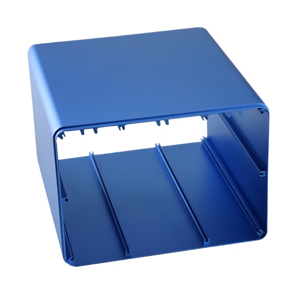
U-shaped cover stiffness comes from the bend radius, not from the wall thickness at the open end
A U-shaped aluminum cover—a channel or trough that slides over a sub-assembly for protection—derives its resistance to bending and twisting primarily from the geometry of the bend region, not from the wall thickness of the straight legs. When a downward force is applied to the center of the open side, the initial deformation mode is opening of the U (the legs splay outward), not bending of the legs themselves. The stiffness of this opening mode is controlled by the bend radius: a tighter radius (R = 1× wall thickness) acts as a near-hinge with very low rotational stiffness, while a larger radius (R = 2–3× wall thickness) distributes the bending strain over a longer arc and increases the moment resistance by 3–5×.
We machine U-covers from solid 6061-T6 plate using a corner-radiusing end mill that establishes the inner bend radius in a single profiling pass. The target radius is 2× the wall thickness (e.g., R3 mm for a 1.5 mm wall) unless the customer’s envelope forces a tighter bend—in which case we add external gusset ribs at the open end to compensate for the reduced bend stiffness. The ribs add about 0.5 minutes of machine time per rib but restore the opening-mode stiffness to match that of a larger-radius design without changing the external envelope.
The open-end dimension tolerance determines whether the cover slides on or must be forced
The most common assembly issue with U-shaped covers is interference fit where a slip-fit was intended. The cover is machined to the nominal internal width (matching the sub-assembly’s outer dimension plus 0.1–0.3 mm clearance), but after anodizing the coating thickness (10–15 µm per surface) consumes 20–30 µm of clearance on each side—enough to convert a 0.2 mm gap into a 0.14–0.16 mm gap, which is still adequate for slip-fit in most cases but leaves no margin for dimensional variation in either part.
If the sub-assembly has a tolerance of ±0.05 mm on its outer width and the cover has a tolerance of ±0.05 mm on its internal width, the worst-case clearance is 0.04 mm—barely enough to assemble without force and certain to bind if either part is slightly out of position or if there is any angular misalignment. We address this by holding the cover’s internal width to the +0.05/+0.15 mm side of its tolerance band (intentionally oversized) before anodizing, so that after coating the as-anodized dimension falls near the middle of the specified range. This requires adjusting the machining program offset based on the measured anodize thickness from the previous batch—a process we have automated with a spreadsheet that calculates the required pre-plate dimension given the target post-plate dimension and the expected coating thickness.
Anodize color matching across cover batches requires controlling both bath temperature and current density
For U-covers that are visible on the final product (consumer electronics, laboratory instruments, automotive interior trim), color consistency between production batches is often more important to the customer than any dimensional tolerance. A natural (clear) anodize finish is relatively forgiving because it depends only on layer thickness, which is easy to control. But colored anodize—especially black, red, and blue—introduces dye absorption variables that can produce visible batch-to-batch variation if not tightly controlled.
The two most significant variables are electrolyte temperature (±2 °C affects dye uptake rate by 10–15 %) and current density (±0.5 A/dm² affects pore structure and therefore dye loading capacity). We maintain the anodize bath at 20 ±1 °C using a chiller with ±0.5 °C stability, and we rack parts at a consistent current density of 1.5 ±0.1 A/dm² by calculating the total racking area for each load and setting the rectifier current accordingly. For red anodize (the most visually sensitive color because the human eye has highest chromatic sensitivity in the yellow-red region), we also add a spectrophotometric check of every tenth part against a master sample, with a pass/fail criterion of ΔE < 2.0 (just noticeable difference under typical indoor lighting).
Edge finish on the open end affects both safety and the ease of sliding the cover onto the sub-assembly
The two longitudinal edges of a U-cover’s open end are the first surfaces that contact the sub-assembly during assembly. If those edges are sharp (as-machined with a sharp insert), they can scratch the sub-assembly’s exterior, gouge any painted or anodized surface, and pose a cut hazard to the assembler’s hands. If they are heavily rounded (large break-edge), the effective internal width at the very edge is reduced, which can cause the cover to initially bind during assembly until it seats fully.
We specify a 0.2–0.3 mm chamfer or R0.3–R0.5 mm break-edge on all exposed edges of U-covers, applied as a dedicated deburring operation using a rotary brush with abrasive nylon filaments (320 grit). This produces a consistent, rounded edge that eliminates sharpness without removing enough material to affect the fit. The operation takes about 15 seconds per part and is integrated into the machining cell’s deburring station so it does not require a separate handling step.
Ventilation slots or holes in the cover walls must be positioned to avoid structural weak points
Many U-covers incorporate ventilation slots or holes to allow heat dissipation from the enclosed sub-assembly. The placement of these features relative to the bend region and to each other determines whether the cover maintains its structural integrity or develops fatigue cracks at the slot ends under thermal cycling.
The rule we follow is: no slot end shall be closer than 3× the wall thickness from any other feature edge (another slot, the bend tangent line, or the cover end). This rule is derived from the stress concentration factor charts for flat plates with edge notches: below 3t separation, the stress fields from adjacent notches overlap and the combined Kt exceeds 4.0, which in 6061-T6 at typical operating stresses (40–60 MPa mean) predicts fatigue life below 10⁵ cycles. Above 3t separation, Kt drops to 2.5–3.0 and fatigue life extends above 10⁶ cycles for the same stress level. When the customer’s drawing places slots closer than 3t, we add a small relief radius (R0.5–R1 mm) at each slot end and note it as an engineering change on the traveler; this reduces Kt by roughly 30 % compared to a square-ended slot.
How we verify that a batch of covers will assemble correctly before shipping
Every batch of U-covers receives a go/no-go assembly check using a hard alloy gauge that represents the maximum material condition (MMC) of the mating sub-assembly. The gauge is machined to the upper limit of the sub-assembly’s outer dimension (nominal + tolerance) and must slide into the cover under hand pressure with no binding. Covers that do not accept the gauge are measured for internal width; if the width is below the lower spec limit, the part is scrapped. If the width is within spec but still binds, the issue is usually angularity (the legs are not parallel) or bow (the base is curved), both of which are correctable with a light re-clamp and re-machine if caught before anodizing.
In addition to the gauge check, we pull one part per 50 for a full assembly trial with an actual sub-assembly (or a surrogate of identical dimensions). The trial confirms that the cover slides on smoothly, the fastening features (clip tabs, screw holes, or snap fits) engage correctly, and there is no interference with any component on the sub-assembly. This 2% sampling rate has caught three drawing-interference issues in the past year that would have caused field assembly problems if not detected pre-shipment.
If you are comparing this part with a machined or welded alternative, the guide to deep drawn covers lays out where drawing wins, where it loses, and what it costs either way.
Specifications
| Item | Anodized Aluminum CNC Machined U-Shaped Cover Case |
|---|---|
| Brand | AUNOV |
| Designing | Send the drawing, or a sample we can measure, a manufacturability review comes back with the quotation. |
| Tooling | Our own toolroom designs and builds every die, with your part number on the tool record. |
| Samples | Pre-production samples ship with dimensional data plus material certs. |
| Materials | Aluminium is the primary stock for this part, alongside carbon steel (SPCC / DC01), 304 / 316 stainless steel, brass and copper, per the drawing. |
| Surface finish | Finish options: plating, e-coat, powder coating, anodising or passivation, as called out on your print. |
| Processing | Multi-stage drawing, annealed in line where wall thinning calls for it, pierced and machined on the same floor. |
| Equipment | Press capacity from 5 to 500 T across mechanical and hydraulic lines, in-house CNC cells and a temperature-controlled inspection room. |
| Tolerance | +/-0.1 mm as-drawn, machined features held to +/-0.03 mm. |
| Delivery terms | FOB is standard; DDP offered for EU and US, payment T/T or L/C, D/P for repeat accounts, call-off scheduling supported. |
Related Products


Request a Quote for This Part
Send a drawing or sketch — get material advice, tooling cost and a per-piece price within 24 hours (working days).