
Anodising is three decisions, and the drawing usually specifies only one
Ask a designer why a machined aluminium bracket is anodized and you will usually hear “for corrosion resistance”. That is one of three reasons, and specifying the finish without separating them produces a purchase order that cannot be executed as intended. Anodizing is simultaneously a corrosion system, a wear system and a colour system, and each of those three demands something different from the process, from the aluminium alloy, and from the drawing. A bracket drawing that says “anodized, black” has actually specified only the third one.
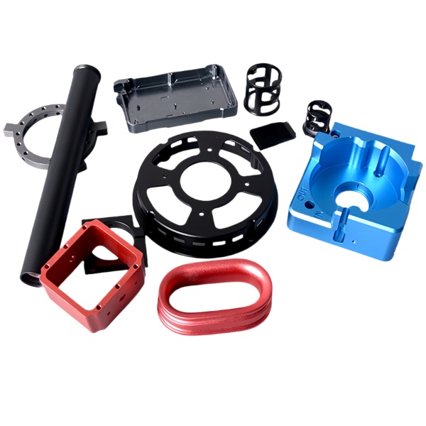
AUNOV machines anodized aluminium brackets and housings from 5052, 6061 and 7075 depending on the structural demand, holding machined features to ±0.03 mm, and applies anodizing per the drawing. This page deals with that interface: where the finish changes what the part is, and what has to be settled before the first chip is cut.
Three purposes, three specifications
| Purpose | What the process has to deliver | Typical specification route |
|---|---|---|
| Corrosion resistance | A continuous, pore-free barrier of adequate thickness, sealed after anodizing | Type II sulfuric anodize, 10 to 15 micrometres, hot sealed; or chromic acid anodize for thin, fatigue-critical parts |
| Wear and abrasion resistance | High surface hardness with real layer thickness, not a cosmetic film | Type III hard anodize, 25 to 50 micrometres, often left unsealed or lightly sealed to retain hardness |
| Colour and appearance | Repeatable colour lot to lot, uniform across geometry, no visible dye pooling or bleed | Type II with a dye, matched to a colour standard, with a specified light source and viewing angle |
These pull in different directions. A colour cosmetic anodize wants a thin, densely dyed layer on a fine-grained alloy; a wear anodize wants a thick layer, which grows more on corners than on flats and therefore rounds edges and changes close-tolerance features. A corrosion anodize wants sealing, which closes the pores and improves the barrier but converts some of the oxide to a hydrated form that reduces hardness. Choosing all three at once means accepting a compromise, and the drawing should say which of the three wins.
Alloy choice decides the colour before the dye does
The single most common disappointment in anodized parts is that two batches of the same part number do not match in colour. The cause is almost never the anodizing line. It is the alloy. The anodic layer is grown from the aluminium itself, so its colour depends on what is in the metal. Iron, silicon, copper, manganese and zinc all participate in the oxide and change its natural tone, and the same nominal alloy from two different mills can differ enough to be visible side by side.
- 6061. The general-purpose machining alloy. Contains magnesium and silicon with silicon in the range of 0.4 to 0.8 percent and copper as an impurity. Takes a dye well and produces a reasonably uniform colour, but the natural oxide already leans slightly grey, and a light tint such as clear or silver will not look identical to the same tint on 5052.
- 5052. Magnesium-based with no copper, and it anodizes to a brighter, cleaner natural tone. It is more formable and less strong than 6061, and it is the better choice when the finish is cosmetic and the load is modest.
- 7075. High strength, containing zinc, magnesium and copper. The copper content makes it harder to anodize to a uniform colour, and thick hard-anodized layers on 7075 are more prone to a yellowish or greyish cast. Use it when strength dictates it and do not expect a perfect cosmetic match to a 6061 part.
- 2024. Highest copper content of the common alloys, and consequently the most difficult to anodize decoratively. Aluminium-copper intermetallic particles oxidize differently from the surrounding matrix and appear as dark specks after anodizing. If the drawing calls for 2024 and a cosmetic finish, one of the two has to change.
The practical rule: if two parts must match in the same assembly, they must be the same alloy and preferably from the same heat lot. Buying anodized brackets from two suppliers to the same drawing, one machining 6061 and the other 5052, is the reliable way to produce a mismatched assembly.
Geometry, current density and the places colour goes wrong
Anodizing is an electrochemical process, so the layer thickness follows the local current density. On a part with sharp external corners, the field concentrates and the layer grows faster; inside a deep pocket or a narrow slot, the field is shielded and the layer grows more slowly. The visual consequence is that the thin parts of the layer take less dye and look lighter, while the corners take more and look darker. On a black anodized bracket, this reads as darker edges and a lighter interior, which the human eye notices immediately even though the layer thickness difference may be only a few micrometres.
The manufacturing implications are specific:
- Aluminium that has been heavily worked, particularly at stamped or formed corners, anodizes differently. The metallurgical structure changes with deformation, and that changes the oxide growth. If a bracket is formed and then machined and then anodized, the formed regions may take colour differently from the cut regions. Knowing this in advance lets us either adjust the surface preparation or warn the customer.
- Deep pockets and blind features need either a higher voltage, a longer dwell, or a design change. A small internal corner in a bracket is a light-coloured spot, and no dye adjustment fixes it. If the appearance of an internal surface matters, the design should either open it up or accept a colour gradient.
- Sharp external edges should be broken before anodizing. A sharp edge builds a thick, brittle layer that is easily chipped, leaving a bright aluminium edge on a black part. A 0.3 to 0.5 mm edge break, applied during machining, prevents the chipping and makes the finished part look deliberate.
- Machining marks show through. Anodizing is a conversion coating, not a filler, so it reproduces the topography beneath it. A face left with a coarse or uneven finish will appear as a coarse or uneven face after anodizing. Where a bracket face is visible, the machining finish should be specified as a finish, not left to whatever the operation produced.
Threads, bores and close tolerances under a growth layer
The anodic layer is grown from the substrate and grows both outward and inward. The commonly quoted split is roughly half outward and half inward, though the exact proportion depends on the alloy and the process. For a Type II coating at 15 micrometres, the practical result is that the surface moves outward by approximately 7 to 8 micrometres and the effective substrate surface recedes by a similar amount. For a Type III hard anodize at 50 micrometres, the outward growth is roughly 25 micrometres per surface.
That has to be reconciled with the drawing’s tolerances. Twenty-five micrometres is 0.025 mm, and a typical machined bore tolerance on this class of part is 0.05 mm total. In other words, a hard-anodized bore can consume half the tolerance band from the finish alone, and a plated thread can consume it entirely.
| Feature | Effect of anodizing | Standard practice |
|---|---|---|
| Precision bore or journal surface | Grows inward and outward, shrinking the bore by roughly the total layer | Mask, or machine undersize by the layer thickness and verify after finish |
| Internal thread | Pitch diameter shrinks; a coated thread will not accept a go gauge | Mask the thread, or specify a pre-plate allowance on the pitch diameter |
| External thread | Pitch diameter grows; may not enter the mating nut | Mask or reduce pitch diameter by the growth before anodizing |
| Sealing face | Hard, slightly abrasive surface; roughness preserved | Mask if an elastomer will move against it; otherwise reduce roughness before finish |
| Electrical contact or ground point | Insulated by the oxide | Mask, or provide a dedicated masking note in the drawing |
| Sharp external edge | Thick, brittle layer, prone to chipping | Edge break of 0.3 to 0.5 mm before anodizing |
Masking is therefore a design deliverable, not a shop-floor improvisation. The most useful single addition to an anodized bracket drawing is a completed masking list: every surface that must not be coated, with the reason. Where a thread must remain conductive or must accept a mating component, that is not a preference, it is a functional requirement, and masking late in the process costs more than designing for it.
Why hard anodize and fatigue resistance disagree
Hard anodizing produces a hard, brittle layer with a different modulus and a different thermal expansion coefficient from the aluminium beneath. Under cyclic loading, the coating tends to crack, and those cracks become stress risers in the substrate. The net effect on a fatigue-loaded aluminium bracket is a reduction in fatigue strength, and the reduction grows with layer thickness. This is a documented behaviour for anodized aluminium and it is why chromic acid anodize, which produces a thinner and more ductile layer, is often specified for fatigue-critical aerospace parts rather than thick sulfuric hard anodize.
For a bracket that sees mainly static load, this is irrelevant and the hard coat is a good choice. For a bracket that sees vibration, cycling, or repeated load reversals — a mounting bracket in a machine, a support in a moving assembly — the following sequence helps:
- Identify the fatigue-critical region and mask it if visual appearance allows, or use a thin anodize there.
- Keep the substrate’s stress level low by adding material or changing the geometry, rather than relying on the coating for strength. The coating contributes essentially no structural strength.
- Break edges in the fatigue-critical region generously, because a coated sharp corner is where cracking begins.
- Consider a shot peening operation before anodizing in genuinely demanding applications; the compressive residual stress from peening offsets the coating’s tendency to crack.
Housings add a fourth consideration: internal environment
When the part is a housing rather than a simple bracket, the anodic layer has to survive a sealed internal environment as well as the outside world. Three points come up repeatedly.
First, a housing that will contain an electronic assembly or a sensor needs its interior coated or deliberately left bare, and the decision is functional. A coated interior is electrically insulating, which is helpful if the housing is also the electrical enclosure, and unhelpful if the housing is the ground return. Second, anodized interiors outgas very little once sealed, which is favourable for sensitive contents, but only if the layer is properly sealed rather than left open-pored. Third, if the housing will be filled with a fluid, the anodic layer’s stability in that fluid at the operating temperature must be checked; the oxide is stable in neutral environments and dissolves in strong alkali, and some hydraulic fluids and coolants are alkaline.
Where a housing needs both an anodized exterior and a machined-function interior, the masking list becomes the central document in the process plan, and it is worth reviewing it with the customer before the anodizing order is placed rather than after.
Verifying the finish is harder than applying it
Anodize verification is where a lot of good intentions stop. The properties that matter — layer thickness, sealing quality, colour match and hardness — are measured by four different methods, and the drawing should name them.
- Thickness. Measured non-destructively by eddy current on a flat witness area, or destructively by microscope on a coupon processed alongside the parts. Because thickness varies with current density, a single reading on a complex bracket is not a full description; specify where the measurement is taken.
- Sealing quality. Checked by a dye stain test, where a dye is applied to the surface, and by an acid dissolution test in a beaker. A poorly sealed coating takes up dye visibly at the surface.
- Colour. Requires a physical standard, a defined light source and a defined viewing geometry. Comparing a finished part to an image on a monitor is not a colour specification, and it is the leading cause of disputes on cosmetic anodizing.
- Hardness and wear. For Type III, micro-indentation hardness is measured on a cross-section, and abrasion resistance can be checked by a Taber test on coupons.
What to put on an anodized bracket drawing
- Alloy and temper, with the same alloy and heat lot required across parts that must match in colour.
- Which of the three purposes dominates: corrosion, wear or appearance.
- Anodize type, nominal layer thickness, and whether the specified tolerances apply before or after the finish.
- A complete masking list with reasons: seal tracks, threads, electrical contacts, ground faces, bearing bores.
- Colour standard with a light source and geometry, plus how many parts constitute an acceptable colour lot.
- Edge break requirement for visible and fatigue-critical edges.
- Surface finish requirement on visible faces before finish, since the finish will reproduce it.
- Any fatigue-loaded region and the anodize treatment specified there.
An anodised scratch cannot be spot-repaired without showing
Can a black anodized bracket be repaired if it is scratched?
Not locally. Anodizing cannot be spot-repaired to an invisible match; a touch-up pen is visible and does not restore the barrier. A scratched part can be stripped and re-anodized, which requires that the part still has enough remaining material to survive stripping and the new growth, and that the tolerances were specified generously enough to allow it.
Is clear anodize really clear?
No. A clear anodize retains the natural tone of the alloy, which is greyish on 6061 and brighter on 5052. It is more accurate to call it undyed. If two parts in clear anodize must match, they must be the same alloy.
How much does anodizing change a tight bore?
Roughly the total layer thickness, split between inward growth and outward growth. For a 15 micrometre Type II layer, allow approximately 0.015 mm on diameter. For 50 micrometres of hard anodize, allow approximately 0.050 mm, which on a small bore can be the entire tolerance. Specify the masking or the pre-finish dimension.
Will anodized threads still work?
They will work if they are masked, or if the pitch diameter is cut undersize before anodizing by the anticipated growth. An unmasked and unadjusted thread will usually fail a go gauge, and it will be stiff in service even when it does assemble.
Does the finish affect the part’s stiffness?
No. The anodic layer is a few tens of micrometres thick and contributes essentially nothing to the section properties. It affects wear, corrosion, appearance, electrical insulation and fatigue initiation, and those are the four conversations the finish should be specified for.
This part belongs to our CNC Machining Parts range. The cnc machining parts pages collect the process notes, common materials and inspection points behind every product in the family.
Specifications
| Item | Anodized Aluminum CNC Machined Brackets and Housings |
|---|---|
| Brand | AUNOV |
| Designing | A drawing file or a physical sample starts the review, the quotation comes back with a manufacturability review attached. |
| Tooling | Dies designed and built in our own toolroom, held and maintained under your part number. |
| Samples | Samples for approval come with dimensional data and material certs. |
| Materials | Aluminium is the primary stock for this part, alongside carbon steel (SPCC / DC01), 304 / 316 stainless steel, brass and copper, with the final grade confirmed at the drawing review. |
| Surface finish | Finish options: plating, e-coat, powder coating, anodising or passivation, as called out on your print. |
| Processing | Deep drawing runs in stages with in-line annealing where the draw ratio requires; piercing and CNC machining stay in house. |
| Equipment | Mechanical presses 5-250 T and hydraulic presses 250-500 T, in-house CNC cells and a temperature-controlled inspection room. |
| Tolerance | +/-0.1 mm as-drawn, +/-0.03 mm after machining. |
| Delivery terms | Standard terms FOB, DDP offered to EU and US, T/T and L/C; D/P on repeat accounts, call-off schedules and blanket orders supported. |
Related Products


Request a Quote for This Part
Send a drawing or sketch — get material advice, tooling cost and a per-piece price within 24 hours (working days).