
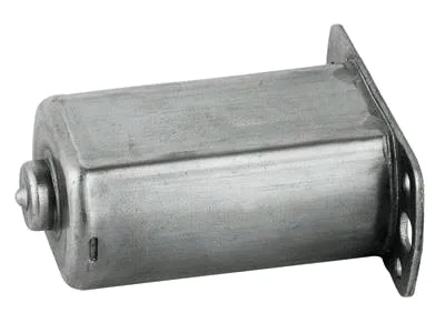
Grease, wear particles and a sealed gear train: the regulator motor body
Inside a power window regulator, the motor drives a worm that turns a wheel, and the power window regulator motor body is what keeps that gear train clean, lubricated and quiet for the vehicle’s life. Its engineering priorities therefore differ from the housings and cases around it: grease retention, wear-particle management, and the sealing interfaces that keep road dust out of a mechanism that runs dry of lubricant at its peril. This page covers the body’s gear-train responsibilities – the ones that decide whether a window still closes quietly in year twelve.
Grease retention: the forgotten functional requirement
A worm drive’s life depends on its lubricant staying in place. Grease in a window regulator faces a hostile schedule: it is flung outward by rotation, migrates along the worm shaft, drips when hot, and thins when the door cavity cools. The body’s contribution is containment – a drawn pocket or a formed lip that defines the grease reservoir around the wheel’s contact zone, boss geometry that blocks the worm’s fling path, and a fill specification (grade, mass, placement) agreed with the gear supplier and inspected on first articles. Motors that develop end-of-life gear noise almost always show a dry wheel contact zone; the grease left the building, and the body let it. Our production includes grease-mass verification by weight difference on sampling, because it is the only cheap way to prove the fill actually happened.
Wear particles: where they go matters
Every worm gear pair generates some wear debris, and the body’s geometry decides where it ends up. Debris that recirculates through the contact zone accelerates wear; debris that migrates to the bearing accelerates bearing failure. The countermeasures are low-tech and effective: a debris trap formed as a low pocket away from the contact path (debris settles rather than recirculates), a labyrinth of formed features that blocks the line-of-sight path from gear to bearing, and smooth (not textured) internal walls so debris does not cling in the contact zone. Field teardowns of quiet-body designs show debris gathered in their traps – quiet, exactly as built. This is design that never appears on a customer’s functional requirement list and always appears in their warranty data if missing.
Sealing interfaces: three joints, three duties
The body presents three sealed or semi-sealed joints, each with a different job. Body-to-housing: the motor’s core joint, sealed against cavity humidity with the flange-and-gasket logic covered on our housing pages. Body-to-output-shaft: a rotary seal or a labyrinth that keeps grease in and water out without dragging on the shaft – labyrinth designs win here for life and cost, provided the formed clearances can be held (typical 0.15-0.3 mm gap bands, achieved by the sizing operations the body’s die already carries). And body-to-end-cover: often a simple overlap with a drain strategy, because the cover’s cavity is where condensate otherwise pools. Specifying all three at RFQ is what lets the die carry their features; specifying them one at a time after tooling is how programmes acquire a sealing patchwork.
The body as the regulator’s structural link
Beyond the gear train, the body carries the regulator’s mechanical reaction. The window’s weight and seal friction resolve into a torque that the body’s mounting features transmit to the rail – and door slam adds its impulse on top. The design answers echo our other body page (load paths from boss to flange, formal radii at roots) with one regulator-specific addition: the output-shaft bearing area sees the highest concentrated load in the assembly, so its wall section and the local emboss that backs it are the body’s most over-engineered features deliberately. Over-engineering one local zone is cheap; a shaft bore that hammers itself loose is the failure mode that ends a regulator’s life.
Grease migrates first, then the geometry shows
The body drawing with the gear train context (worm and wheel dimensions, grease specification, fill placement), the three sealing interfaces, the regulator’s reaction torque and door-slam spec, and volume. First articles in three to four weeks after die approval, with grease-mass verification and seal-gap metrology included for gear-train programmes.
Regulators get noisy near end of life
Our regulators get noisy near end of life – is it grease or geometry?
Usually both in sequence: grease migrates, then the geometry fails to trap the debris, then the contact zone wears. We can section returned parts and read the sequence – the trap tells which design was missing.
Can you hold the output-shaft labyrinth clearance?
Yes, at 0.15 mm minimum gap, with the sizing operations the body already runs. Tighter than that risks rubbing; looser leaks debris. The window is narrow and we design to it.
Do you fill grease?
We fill and verify on qualifying volumes, to the gear supplier’s specification, with mass verification sampled and certificates filed. Placement geometry is part of the body’s tooling, which is why the fill spec belongs at RFQ.
This part belongs to our Automotive Motor Components range. The automotive motor components pages collect the process notes, common materials and inspection points behind every product in the family.
Specifications
| Item | Power window regulator motor body |
|---|---|
| Brand | AUNOV |
| Designing | Your drawing sets the part – samples are reverse-measured into a controlled drawing; revisions are re-quoted once rather than silently absorbed. |
| Tooling | Our toolroom covers die design, wire-cut EDM and maintenance, so tooling lead time stays under our control, and maintenance is tracked against the part number. |
| Samples | Prototype and pre-production samples are provided against the drawing, so the approved first article becomes the gauge reference, and later batches are gauged back to the signed sample. |
| Materials | Carbon steel (SPCC / DC01), 304 / 316 stainless steel, aluminium, brass and copper – the grade is matched to the duty of this regulator. |
| Surface finish | Plating, coating or polishing to suit the drawing – zinc, nickel, chrome, anodising, passivation or e-coat. |
| Processing | Blanking, multi-stage deep drawing with interstage annealing, trimming and piercing, coining, then finishing. |
| Equipment | Presses from 5 to 250 T mechanical and 250-500 T hydraulic, annealing ovens on site, plus CNC turning and machining centres. |
| Tolerance | +/-0.01 mm to +/-0.03 mm on controlled dimensions, with CMM reports and capability data for critical features. |
| Delivery terms | CIF or DDP, with FOB available, payment by T/T or L/C, quoted in USD or EUR; repeat orders reuse the approved first article. |
Related Products


Request a Quote for This Part
Send a drawing or sketch — get material advice, tooling cost and a per-piece price within 24 hours (working days).