
Door slam, road shock, fifteen years: enclosure survival in a regulator
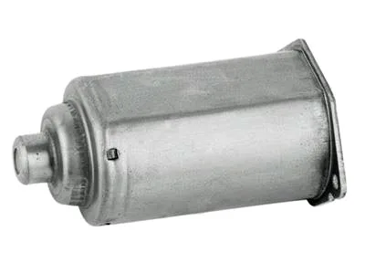
The most violent regular event in a window motor’s life is not the motor running – it is the door closing. A slam sends a shock impulse through the regulator rail, into the power window regulator motor enclosure, and out through its mounting features, thousands of times over a vehicle’s life. Enclosure engineering for this family therefore starts with shock, continues with vibration, and finishes with the module-assembly practicalities that decide whether the enclosure installs cleanly on the regulator line. This page covers the three in that order.
Shock design: the slam spectrum
A hard door close delivers a half-sine impulse of several tens of g at the enclosure’s mounting points – short enough that the enclosure’s response is governed by its local stiffness, not its mass. The vulnerable features are predictable: long unsupported flange spans (they flex and fatigue at the root), snap or bolt bosses formed from thin wall (they crack at the extrusion shoulder), and any mass cantilevered off the shell – a solenoid, a relay, a connector housing. Our enclosure designs answer with formed ribs running from boss to flange (load paths, not decoration), boss shoulders radiused at 0.5 mm minimum, and cantilevered masses supported by a formed bracket tied to two walls rather than one. The validation is a shock rig test at the customer’s specified g-level and pulse shape, on parts mounted exactly as the regulator mounts them – because a fixture-mounted enclosure passes tests that a rail-mounted one fails.
Vibration: the regulator’s own signature
Beyond slam shock, the enclosure lives on a regulator that generates its own vibration – gear mesh impulses through the drive train, glass-seal friction spikes, and the motor’s electromagnetic ripple. The enclosure’s job here is the quiet one: not to add resonances. We run a modal survey on first articles (hammer tap, response mapping) and check that no enclosure mode sits near the gear mesh frequency or the motor’s torque-ripple harmonics; where one does, a rib or a wall-thickness zone moves it. The step is cheap at design time and invisible at launch – which is exactly the point. Programmes that skip it meet their resonances at the vehicle level, where the fix involves the whole door module and everyone’s schedule.
Module assembly: designing for the regulator line
The enclosure meets the regulator as a sub-assembly operation, and its features either help or hinder. What helps: a spigot or locating feature that aligns the enclosure to the rail without fixtures (assemblers self-locate, cycle time drops), fastener features with formed lead-ins, and a cable-exit oriented to the harness’s natural route with a grommet seat sized to its supplier’s print. What hinders: any feature requiring an inspection decision (assemblers do not measure), symmetric geometry that can be installed rotated (add an asymmetric witness), and fasteners accessible only with an angle driver. These are line-trial findings from decades of regulator programmes, and they cost nothing to include at die design.
Corrosion in the protected cavity – revisited for enclosures
The door cavity’s cyclic condensation, covered on our case page, applies to the enclosure with one addition: the enclosure often touches or nearly touches the regulator’s steel rail, creating a galvanic pair in a humid film. The defences are coating selection compatible with the contact (zinc-nickel on the enclosure when the rail is bare steel, or an isolating washer), and drainage-friendly geometry so condensate does not pool at the contact line. We ask for the rail’s material and finish at RFQ – the enclosure’s coating spec is a system decision, and pretending otherwise is how crevice corrosion photos end up in warranty files.
The boss shoulder radius is where the crack starts
The enclosure drawing, the regulator’s mounting context (rail material and finish, fastener access, harness route), the shock and vibration specs from the door-module validation plan, and volume. First articles in three to four weeks after die approval, with the modal survey included when the programme carries a noise budget.
Enclosures crack at a boss after door-slam testing
Our enclosures crack at a boss after door-slam testing – fixable in the draw?
Usually: the boss shoulder radius and its supporting rib are die geometry. Send the cracked parts; the fracture surface shows whether it is shock overload (fixable) or fatigue from a resonance (fixable differently).
Can you integrate the relay or connector housing?
For formed sheet versions, yes within limits – a relay pocket with clip features is routine. Complex connector bodies remain moulded parts; we would rather say so than form a poor copy.
Do you supply enclosures pre-assembled to the regulator?
On qualifying volumes we can assemble and torque-check to your specification – it moves the line work to us, and the quote shows the increment honestly.
This part belongs to our Automotive Motor Components range. The automotive motor components pages collect the process notes, common materials and inspection points behind every product in the family.
Specifications
| Item | Power window regulator motor enclosure |
|---|---|
| Brand | AUNOV |
| Designing | Made to your 2D/3D drawings (PDF, DWG, STEP, IGS) – a manufacturability review comes back with the quotation; the agreed version governs every later batch. |
| Tooling | Tooling is built and held under your part number, so die cost stays transparent, and the die remains dedicated to your part. |
| Samples | First-article samples ship with a dimensional report and material certificate, so the sample is retained as the master, and mass production is gated on that approval. |
| Materials | Carbon steel (SPCC / DC01), 304 / 316 stainless steel, aluminium, brass and copper – the grade is matched to the duty of this enclosure. |
| Surface finish | Plating, coating or polishing to suit the drawing – zinc, nickel, chrome, anodising, passivation or e-coat. |
| Processing | Deep drawing from coil or blank, with in-process annealing so walls thin evenly; trim, pierce, form and finish. |
| Equipment | The press floor pairs 5-250 T mechanical with 250-500 T hydraulic presses; an in-line annealing furnace sits on line and CNC turning covers secondary work. |
| Tolerance | +/-0.01 mm to +/-0.03 mm on controlled dimensions, with CMM reports and capability data for critical features. |
| Delivery terms | FOB Ningbo or Shanghai, T/T with deposit and L/C for larger runs; each volume tier carries its own quoted price. |
Related Products

Request a Quote for This Part
Send a drawing or sketch — get material advice, tooling cost and a per-piece price within 24 hours (working days).