
What happens to metal when you draw a motor can
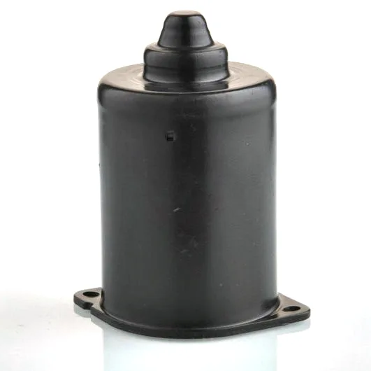
A wiper motor can – the deep cylindrical shell that carries the field magnets and closes the magnetic circuit – is the purest deep-drawing exercise in the motor. No ears, no slots, no local forms: just a straight-walled cylinder, drawn from a disc, expected to stay round, thin, and magnetically useful for the life of the vehicle. That simplicity is deceptive. Everything that can go wrong in deep drawing concentrates in a can, which is why it makes such a good diagnostic part for judging a stamping supplier.
The physics in four numbers
- Draw ratio. A typical can draws at 1.8-2.1 blank-to-punch. Below 1.9 is routine single-stroke territory; the 2.0-2.1 band works with a well-tuned bead and good lubricant; beyond 2.1 the honest answer is a two-stroke draw.
- Wall thinning. The critical zone above the punch radius thins 3-8% in a healthy draw. Magnets sit inside the can with their own clearance, so thinning matters less mechanically – until the can doubles as the yoke, where a thin wall means a fat flux gap and torque loss measured at the bench.
- Earing. Rolled sheet’s anisotropy grows four ears on the flange at 90° intervals, typically 2-4% of diameter. On a can that gets trimmed flush this is only scrap; but the ear height tells us the sheet’s r-value band, so we read it as free process data every stroke.
- Springback. A can’s open end flares a few tenths when the punch retracts. The trim die sizes it out; the parameter to watch is flare consistency, which signals die wear before bore drift does.
The can as half of a magnetic circuit
In a permanent-magnet wiper motor the can’s steel closes the flux loop between magnets. Two material properties therefore matter beyond formability: permeability, which argues for a low-carbon ferritic steel, and thickness uniformity, because the magnet-to-can gap is set at assembly and a wall that wanders changes the air gap locally. This is also why we counsel against 300-series stainless steel cans – the draw is fine, the corrosion is superb, and the motor loses torque into a non-magnetic return path. Where a stainless steel can is genuinely required, 1.4016 ferritic is the family that keeps the flux path intact.
Volume reality: the can is a numbers game
Cans run fast. On our presses a wiper can stamps in well under a second, and the economics live in uninterrupted streaks: coil changeovers timed, lubricant metered, scrap weighed per shift. A can programme that runs clean loses under 0.5% to splits and wrinkles; one that runs at the edge of its draw window loses several percent and, worse, loses it randomly. We front-load the stability work – simulation before die steel, blank development tuned to kill earing asymmetry, lubricant specified by grade – because a can die that starts stable stays stable, and one that starts marginal ages fast.
Secondary operations that cans actually need
Most cans leave the draw needing three things: a flange trim to length (with the trim tool sized to the flared end, not the nominal), magnet-pocket or keyway features if the design locates magnets in the wall, and a bore-end chamfer or curl if the design closes against an end-bell. Cans with wall-located magnet pockets are a different die class – the pockets pierce-and-form after draw while the shell is strip-supported – and we quote them separately because the tooling geometry changes fundamentally.
Punch and die diameters, and the material’s own spread
Can diameter, depth, wall thickness, material family (and if magnetic performance matters, say so explicitly – it changes the steel), volume, and whether magnets locate in the wall. With that, we return a draw-ratio verdict, tooling quote, and a sample timeline; first articles typically run three to four weeks after die approval, and cans are the part family where first articles nearly always ship conforming.
Reading the shell: what inspection tells a can programme
Because a can has so few features, inspection reads process health rather than pass/fail. Wall thickness mapping by ultrasonic spot-check shows where the draw window sits; ear height on the untrimmed flange reports the coil’s anisotropy batch by batch; ovality before trim predicts how much work the restrike will do. A can programme that tracks those three signals sees die wear and coil drift weeks before they become scrap, which is why we chart them per shift on every can volume we run.
Why does the current supplier’s can vary in wall thickness?
Why does our current supplier’s can vary in wall thickness at the bottom?
That is the thinning zone; variation there means the draw window is drifting – usually lubricant, occasionally coil batch. It is fixable, but it is a process-control conversation, not a receiving-inspection one.
Can you draw a can in one stroke at ratio 2.1?
Sometimes, and we will prove it in simulation before promising. If simulation says marginal, we quote a two-stroke die; the piece-price difference is smaller than the scrap rate of a die that lives at its limit.
Do you supply cans already fitted with magnets?
We can bond and gauge magnets as a value-added step on qualifying volumes; the magnet sourcing usually stays with the motor maker, and the bonding jig is programmed to their magnet set.
Automotive Motor Components is the parent range for parts like this one; the overview page gathers the tooling logic, finishing options and tolerance notes that apply across the family.
Specifications
| Item | Wiper motor can |
|---|---|
| Brand | AUNOV |
| Designing | Your drawing sets the part – DFM notes are returned before any tooling is cut; changes are priced before they are made. |
| Tooling | Dies, fixtures and gauges are made in our own toolroom, so die cost stays transparent, and first-article timing is measured from the tooling start date. |
| Samples | First-article samples ship with a dimensional report and material certificate, so the part is proven before it is made in volume, and later batches are gauged back to the signed sample. |
| Materials | Carbon steel (SPCC / DC01), 304 / 316 stainless steel, aluminium, brass and copper – the grade is matched to the duty of this can. |
| Surface finish | Zinc or nickel plating for corrosion, plus powder coating or electrophoresis on housings; laser etching on request. |
| Processing | Coil blanking, progressive drawing through 3-5 stages with anneals between, trim and pierce, then deburr and finish. |
| Equipment | Mechanical capacity 5-250 T and hydraulic 250-500 T, with annealing ovens and CNC turning and machining centres alongside. |
| Tolerance | +/-0.1 mm on formed features and +/-0.2 mm on overall lengths; tighter bands confirmed against the die before quoting. |
| Delivery terms | CIF or DDP, with FOB available, payment by T/T or L/C, quoted in USD or EUR; sea or air freight is quoted to your door. |
Related Products

Request a Quote for This Part
Send a drawing or sketch — get material advice, tooling cost and a per-piece price within 24 hours (working days).