
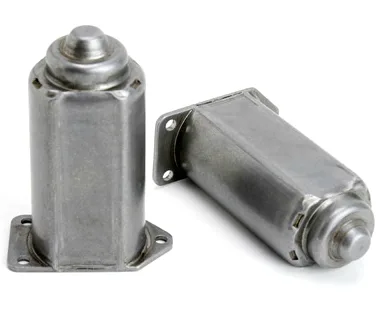
A connector shell is a machine, and the mating half has to be in it too
A deep drawn connector is one of the few products in this family where the drawing describes only half of the thing that determines whether it works. A connector is a pair – a shell and a terminal or mating insert – and its performance comes from properties that belong to the pair rather than to either part: how much of the shell’s circumference the terminal actually engages, how the two halves align when they are brought together, and whether the shell holds the other one with enough force to resist vibration without needing a separate locking mechanism.
We deep draw from coil or blank with in-process annealing so walls thin evenly, running 5-250 T mechanical and 250-500 T hydraulic presses with annealing ovens on site, CNC turning centres for secondary operations, and CMM inspection. First articles verify the whole flow before the run is released, formed features are held to +/-0.05 mm with capability data on critical dimensions, and finer bands are confirmed from capability data before quoting. Standard stock is carbon steel in SPCC and DC01 grades, 304 and 316 stainless steel, aluminium and brass, with mill certificates and heat numbers accompanying the first article. Drawings are reviewed for feasibility, and the agreed version is what production runs against.
The four properties a connector shell must deliver
- Contact normal force. The terminal’s spring force against the mating contact determines the electrical reliability. The shell contributes by setting how far the terminal is deflected – too little engagement and the contact force falls below the required value; too much and the insertion force becomes unmanageable and the terminal is over-stressed.
- Insertion and withdrawal force. This is the pair’s property, and it is a mechanical-interference question. It has to be high enough to hold the halves together against vibration and handling, and low enough that the assembly line can mate them without damage. These two requirements pull against each other, which is why connector designs are usually a compromise and why the tolerance structure matters more here than on almost any other part.
- Alignment. The two halves have to come together without the contacts touching before they are properly seated. This is a positional requirement between features on two different parts, so it depends on the shell’s own datum scheme and on the mating part’s – and on the tolerance stack across both.
- Polarisation. The halves must only fit together the right way round. On a connector this is achieved by keying – a feature on the shell that physically prevents the wrong orientation. It is a design feature rather than a tolerance, and it is one of the cheapest safeguards against assembly error.
Where the tolerance budget actually goes
A connector shell is usually drawn with a formed-features band of +/-0.05 mm, and the interesting question is which features those are. The features that consume budget:
| The bore the terminal sits in | Set by the draw, so it is a tooling dimension. Its size controls the terminal’s support and therefore part of its spring behaviour. |
|---|---|
| The keying feature | A formed or machined feature whose position must be controlled relative to the bore. A key that is off by a fraction will still prevent mis-orientation – it is a binary function – but a key that is too shallow or worn will not, and it has to be robust rather than precise. |
| The rim or flange that butts against the mating half | This is the shell’s axial locating feature and the one whose position most directly affects alignment. It is frequently the tightest dimension on the part. |
| The outer diameter and roundness | Where the shell fits into a panel cut-out or into a moulded surround, the OD and its roundness control whether it mounts. |
| Any latch or retention feature | A dimple, a lanced tab or a drawn bead. Its position controls retention force, and its force is a function of the material’s condition rather than just its geometry. |
Where a finer band is genuinely needed – on a rim that positions the mating half, for example – it is confirmed from capability data before quoting. That is worth taking seriously as a customer: asking to see the capability on a specific dimension before ordering is far cheaper than discovering after the first thousand pieces that the process mean sits too close to a limit.
Materials: conductivity, corrosion and the contact environment
Standard stock is carbon steel in SPCC and DC01 grades, 304 and 316 stainless steel, aluminium and brass, with mill certificates and heat numbers accompanying the first article. For a connector shell the material choice is driven by where the shell sits relative to the contact:
- Brass. The most common choice for a shell that conducts current, where the shell is part of the electrical path, or where a good bearing surface for a latch is wanted. Brass’s conductivity and its corrosion resistance in ordinary air make it the default for many connector designs, and it machines well for the secondary features.
- Stainless Steel 304 or 316. Where the connector is in a wet or corrosive environment, or where a sealed connector body has to survive washdown or immersion. 316 for chloride exposure. Note that the shell is usually not the electrical path – the terminal is – so conductivity is often irrelevant and corrosion resistance dominates.
- Carbon steel. Where the shell is purely structural or shielding and the environment is dry. Needs plating or coating, and where it sits near a contact the coating must not reach the contact region.
- Aluminium. For weight and for shielding applications. Anodising gives good corrosion protection and a hard surface, and it must be masked from any bearing or contact surface.
Finishing: the dimension problem is unavoidable here
Finish selected from the drawing – plating, coating, anodising or passivation – with the finish inspected alongside the dimensional report on the first article. On a connector shell the finishing decision and the tolerance decision are coupled, because:
- Plating changes every external dimension, and on a shell that must fit a moulding or a panel cut-out, that is a real fit change. The drawing must state whether the dimensions are before or after finishing.
- The bore usually must not be plated. A plated bore is smaller and rougher, and it will affect how the terminal sits. Mask it, or specify it as a pre-plate dimension.
- Any rim or locating face that butts against the mating half should be masked, since a coating film there changes the axial position and the contact force.
- A latch or retention dimple changes force with coating thickness as well, and a coating on a dimple changes the wear behaviour over repeated mating cycles.
- Masking on a small drawn part is not free. It may be a plug, a tape operation, or a rack. It belongs in the cost and it belongs on the drawing.
Drawn construction and what it means for a shell
The route is deep drawing with in-process annealing, and three consequences for a connector shell specifically:
- Wall thickness varies and is predictable. The wall at the punch nose is thinnest. On a shell where the terminal bears against the bore, the bore’s remaining wall – not the nominal – is what governs the terminal’s support.
- The bore’s roundness is good, because a punch-formed bore is one of the better-made features in stamping. Its size is a tooling dimension, so it is consistent between batches but only as accurate as the punch.
- A drawn shell is stiff and consistent, which is why it holds alignment better than an equivalent moulded or turned shell. This is a genuine advantage of the drawn process for this product and is worth recognising rather than treating as an aesthetic choice.
How to get a connector shell right first time
Drawings are reviewed for feasibility and the agreed version is what production runs against. Tooling is built and held under your part number, so tooling lead time stays under our control and the die remains dedicated to your part. Pre-production samples come with a full inspection report, the part is proven before it is made in volume, and later batches are gauged back to the signed sample.
Seven things that turn a connector shell drawing into a manufacturable one:
- The mating part’s dimensions, or at least its key dimensions and tolerances. Without these, the alignment and insertion-force requirements cannot be assessed – and they are properties of the pair.
- Which features are functional, specifically the rim that locates axially, the bore that supports the terminal, and the keying feature.
- Whether dimensions are before or after finish, and which surfaces are masked.
- Any retention feature’s required force, stated as a force rather than as a dimension – because force is what it is for.
- The material, decided on whether the shell is in the electrical path and on the environment, not by default.
- Polarisation: whether the design requires keying against mis-orientation, and if so how it is achieved.
- The contact environment, including whether the shell will be plated, sealed, or potted – all of which change what the dimensions can be allowed to do.
The general principle worth taking away: a connector shell is specified in isolation but designed as a pair. A shell drawing that includes the mating part’s requirements is a shell drawing that can be reviewed properly, and a shell drawing that does not will be quoted and made correctly and may still not work.
Drawing, machining and welding each win on different geometries; the guide to deep drawn covers works through those boundaries, and the full Precision Deep Drawn Parts range is reachable from the overview page.
Specifications
| Item | Deep Drawn Connector |
|---|---|
| Brand | AUNOV |
| Designing | Drawings are reviewed for feasibility, and the agreed version is what production runs against. |
| Tooling | Tooling is built and held under your part number, so tooling lead time stays under our control, and the die remains dedicated to your part. |
| Samples | Pre-production samples come with a full inspection report, so the part is proven before it is made in volume, and later batches are gauged back to the signed sample. |
| Materials | Standard stock: carbon steel (SPCC / DC01), 304 / 316 stainless steel, aluminium, brass; mill certificates and heat numbers accompany the first article. |
| Surface finish | Finish selected from the drawing: plating, coating, anodising or passivation; the finish is inspected with the dimensional report on the first article. |
| Processing | Deep drawing from coil or blank, with in-process annealing so walls thin evenly; first articles verify the whole flow before the run is released. |
| Equipment | Press shop running 5-250 T mechanical and 250-500 T hydraulic presses, annealing ovens on site, with CNC turning centres for secondary operations and CMM inspection. |
| Tolerance | +/-0.05 mm on formed features, with capability data on critical dimensions; finer bands confirmed from capability data before quoting. |
| Delivery terms | CIF or DDP, with FOB available, payment by T/T or L/C, quoted in USD or EUR; repeat orders reuse the approved first article. |
Frequently Asked Questions
Why is a connector shell only half the product?
A connector is a pair – a shell and a terminal or mating insert – and its performance comes from properties belonging to the pair: how much of the shell’s circumference the terminal engages, how the halves align, and whether the shell holds with enough force to resist vibration. The drawing describes only the shell.
What four properties must a connector shell deliver?
Engagement of the terminal, alignment of the two halves, retention force against vibration, and the contact environment’s corrosion resistance. These pull the tolerance budget toward the mating interface rather than the outer wall.
Which materials are used for connector shells?
Carbon steel in SPCC and DC01, 304 and 316 stainless steel, aluminium and brass, with mill certificates and heat numbers on the first article. Formed features are held to +/-0.05 mm with capability data on critical dimensions.
How is a connector shell verified first time?
First articles verify the whole flow – draw, CNC and the mating interface – before release, and the shell is reviewed for feasibility against the mating half. The typical minimum order is 1,000 pieces with a 24-hour quotation.
Related Products



Request a Quote for This Part
Send a drawing or sketch — get material advice, tooling cost and a per-piece price within 24 hours (working days).