
The number that decides a machining quotation is setups, not features
Ask most people why one machined part costs more than another with the same material, the same tolerance and the same number of features, and the answer is usually feature count or tonnage. On a CNC turning route the more accurate answer is the number of times the part has to be let go and re-clamped. Every setup is a new datum, a new set of errors and a new handling risk, and it is also a large fixed cost that a bar-fed machine pays on every single part. Reducing setups is therefore the single highest-leverage act in designing a machined part, and it is a decision made on the drawing rather than on the machine.
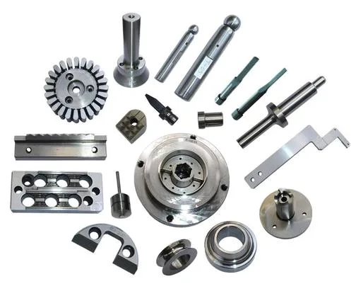
This page covers general machining parts made on bar-fed CNC turning centres with milled features completed in the same clamping, plus 3- and 4-axis machining centres, with inspection in a climate-controlled inspection room. We hold +/-0.02 mm general machining with tighter bands on flagged dimensions, and capability is checked on the first article before the run continues. Grade and temper are confirmed in writing before tooling, first-article samples ship with a dimensional report and a material certificate, and every stage is logged against your part number.
Why a second setup costs so much
Each additional setup brings four costs, and they compound:
- Datum transfer. A part machined in one clamping has every feature related to every other feature by the machine’s own accuracy and by the part’s rigidity on that spindle. A part machined in two clampings has the relationship between setups set by where the operator put the part the second time. That single fact explains most of the tolerance failures on machined parts.
- Time. Bar feeders are automated and a machine runs unattended. A part that has to come off, go to a mill, get fixtured, and come back costs an operator’s time and a queue, not just a spindle time.
- Handling and damage. Every transfer is a chance to mark a finished surface, to drop a part, or to burr a feature that was supposed to be complete.
- Error accumulation. Each setup contributes its own runout and positioning error to the finished part.
This is why the phrase “milled features completed in the same clamping” appears in our processing description. It is a design commitment, not a convenience: if a part’s holes, flats and slots can all be reached from one setup with the part held in one orientation, they should be, and the drawing should be arranged to make that possible.
Designing for one setup
The useful design moves are mostly free:
- Put every feature the part needs on the same axis or the same face. If a bolt circle and a cross-hole can both be made from the same end, they can be made in one setup. If one is on the other end of the part, that is a second setup, and moving the feature or making the part longer to hold both may be cheaper.
- Add a flat so the part can be clamped on a surface that is not a functional face. A clamping flat costs material and costs nothing in tolerance, and it removes the reason to clamp on something that matters.
- Combine the turned and milled features. A turn-mill machine can turn a diameter and mill a slot in the same clamping, which on a part like this is the difference between one operation and two.
- Specify a datum that the process can actually hold. A drawing that locates everything from a face that is itself machined in the second setup has built in an error. Locating from the largest and most stable feature is nearly free.
- Avoid features that need a different kind of machine. A part that needs both a turned feature and a deep pocket in a difficult orientation may be cheaper as two parts welded together, and it is worth pricing that option rather than assuming one piece is always better.
General tolerance, and what “flagged dimensions” means
We hold +/-0.02 mm as a general machining band, with tighter bands on dimensions the drawing flags. This is a practical arrangement rather than a philosophical one, because on a part with a mix of features, holding the tightest band everywhere is usually unnecessary and always expensive. It raises tool wear, forces slower feeds, and can push a part into a different material condition or a different operation.
The flagging is worth thinking about from the design side. The dimensions that usually deserve a tighter band are the ones that a mating part depends on:
| A bore or shaft that locates another part | This is the tightest dimension on most machined assemblies, because it controls fit. Often flagged at a band several times tighter than the general tolerance. |
|---|---|
| A sealing face | Both its flatness and its size, because a seal needs both. Flatness is a separate call from size and is not implied by it. |
| A threaded feature’s effective diameter | Thread size does not guarantee fit. What matters is the pitch diameter, and where fit matters it has to be called out. |
| Anything an inspection fixture locates on | Including the datum features themselves. A datum that moves makes every controlled dimension move with it. |
One thing that is worth writing down explicitly: whether a dimension applies before or after surface treatment. Plating, coating and anodising all change a surface, and on a dimension of +/-0.02 mm a coating film is a significant fraction of the band. This is the most common avoidable ambiguity on a machining drawing, and it is resolved by one line.
Materials, and the machinability question that actually matters
Carbon steel in SPCC and DC01 grades, 304 and 316 stainless steel, aluminium and brass are all held, and the grade and temper are confirmed in writing before tooling. What the choice changes on a machining route:
- Free-machining grades exist and are worth asking about. A grade with a sulphur addition chips cleanly, cuts faster and holds a surface better than a standard grade – and on a stainless steel part that is cut in volume, the cycle-time difference can be substantial. The trade-off is that free-machining grades are not suitable for some corrosion duties and can be unsuitable for welding, so it is a functional decision rather than a purely economic one.
- Stainless Steel work-hardens. A stainless steel part that is interrupted mid-cut becomes harder at the interruption, and a dull tool makes it worse quickly. This is why a stainless steel machining quote should assume continuous cycles and sharp tooling, not interruptions.
- Aluminium is fast but needs care. It cuts well and at high speed, but it machines with a tendency to grab and to weld to the tool at the exit of a cut, particularly on a thin or interrupted feature. Sharp tooling and a suitable coolant are not optional.
- Brass and copper. Free-cutting and pleasant to machine at speed, and copper’s thermal conductivity means heat goes into the work rather than the tool. Both are gummy and need a sharp positive rake.
Finishing, and the operation it adds
Surface treatment matched to the duty – plating, coating or polishing – with finish thickness and adhesion checked on the first article. Three things to settle on a machined part before quoting:
- Masked areas. Threads, sealing faces, bores that a shaft will enter, and any datum that must stay a true size. Masking is a planned operation and a cost.
- Size before or after finishing. Already mentioned, and it is the one to be certain about.
- Which operations happen before and after finishing. A part that is masked has to be masked at a specific point, which fixes the sequence. A tapped hole that is machined after plating will have a slightly different fit than one plated after tapping.
Where a part is machined and then used as-is, deburring is the finishing question rather than coating, and on a machining route the burr has to be removed in a way that does not round the edge the drawing depends on – a small chamfer that is specified is better than a deburr that is not.
From drawing to first article
Send drawings, or send a sample to be measured. A manufacturability review comes back with the quotation, and the agreed version governs every later batch. Progressive and drawing dies are designed and built in house, so a die can be re-cut against the approved drawing and maintenance is tracked against the part number – which on a machined part matters mainly for the fixtures and gauges rather than the cutting tools, since a worn fixture is the quiet cause of a drifting dimension.
Three questions that most improve a machined part before it is quoted: which face or feature is the datum everything else is measured from; which dimensions are actually tight enough to need flagging; and whether the part can be completed without coming off the machine. Answer those three and the process plan, the cost and the capability all follow.
This part sits inside our CNC Machining Parts range. Across the cnc machining parts pages you will find the process notes, common materials and inspection points behind every product in the family.
Where this part is used
General machining parts are the category of work where the customer rarely needs a specific geometry explained to them – they need the same thing as usual, done repeatably. What varies from job to job is not the shape but the economics of getting to it: how many times the part has to be set up, what tolerance is genuinely needed on which dimension, and whether the finish adds an operation. On that basis most machining quotes are decided before anyone looks at a feature list.
The parts that arrive here tend to be the ones already proven somewhere – a machined fitting, a turned body with a keyway, an aluminium block with bored ports – either because a production run needs a second source, or because the original supplier has moved on. That history is useful: the drawing usually exists and the tolerance usually has a reason behind it, even if the reason was never written down.
What we need to quote it
Send the drawing with the critical dimensions flagged and the material grade and temper confirmed in writing before tooling. Tell us the annual quantity and whether a repeat order is likely, because that changes the setup strategy. First-article samples ship with a dimensional report and a material certificate, and production starts only after your written sign-off – so tell us who signs off and when, because that is often where the schedule really sits.
Specifications
| Item | Machining parts |
|---|---|
| Brand | AUNOV |
| Designing | Send drawings, or send a sample to be measured – a manufacturability review comes back with the quotation; the agreed version governs every later batch. |
| Tooling | Progressive and drawing dies are designed and built in house, so a die can be re-cut against the approved drawing, and maintenance is tracked against the part number. |
| Samples | Samples for approval come with a dimensional report and material certification. |
| Materials | Materials held include carbon steel, 304 / 316 stainless steel, aluminium and brass; grade and temper are confirmed in writing before tooling. |
| Surface finish | Surface treatment matched to the duty: plating, coating or polishing; finish thickness and adhesion checked on the first article. |
| Processing | Bar-fed turning with milled features completed in the same clamping; first articles verify the whole flow before the run is released. |
| Equipment | Bar-fed CNC turning centres plus 3- and 4-axis machining centres, backed by CNC turning centres and a climate-controlled inspection room. |
| Tolerance | +/-0.02 mm general machining, tighter on flagged dimensions; capability is checked on the first article before the run continues. |
| Delivery terms | CIF or DDP, with FOB available, payment by T/T, L/C at sight or D/P; call-off schedules are supported. |
Related Products


Request a Quote for This Part
Send a drawing or sketch — get material advice, tooling cost and a per-piece price within 24 hours (working days).