
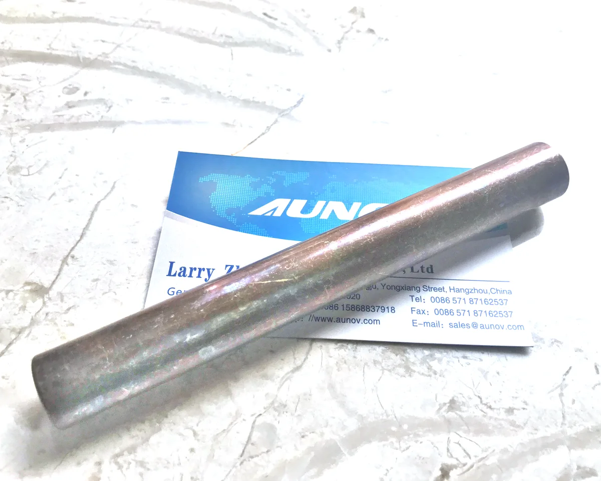
Brass tube: a pressure part that also has to look right
A deep drawn brass tube sits somewhere between a fluid component and a finished product, and the reason it sits there is a property combination that nothing else offers: it conducts heat, it resists corrosion in most ordinary media, it machines to a fine surface, it takes a plating or a polish, and it can be drawn to a thin wall with a good surface. That combination is why brass tube appears in fuel and hydraulic lines, in instrument and gauge tubing, in air and gas fittings, in heat exchanger work, and in decorative and architectural trim – often in the same industry.
We draw these progressively through several stages with annealing between draws, then trim and pierce, logging every stage against your part number. H62 and H65 are held across 0.8-4.0 mm, selected for conductivity, fine surface detail and corrosion resistance. Turned secondary features run to +/-0.03 mm and as-drawn walls to +/-0.1 mm, and inspection is on the CMM. This page covers the four questions that decide whether a brass tube drawing is complete.
Wall thickness is a pressure decision
On any tube that carries fluid under pressure, the wall is not a stiffness choice – it is a strength and a fatigue choice, and it should be calculated rather than selected by convention. Two failure modes compete, and which one governs depends on the situation:
| Burst under internal pressure | Hoop stress governs. For a thin-walled tube the relationship is direct: increasing wall by a factor of two approximately doubles the burst pressure. The calculation uses the alloy’s yield strength at the actual operating temperature, not at room temperature – a significant correction on a hot line. |
|---|---|
| Fatigue under pressure cycling | Alternating pressure cycles fatigue the wall, and the failure life is dominated by the stress range at each surface, by the wall’s freedom to deform, and by everything that puts a notch on the inside or outside. A tube supported at only one end and free at the other flexes under its own weight and adds bending stress to the pressure stress. |
| Corrosion fatigue | Where the medium is corrosive, the fatigue life drops sharply and the material’s corrosion allowance has to be added on top of the pressure requirement. This is the case where brass’s good general corrosion resistance becomes the thing you have to check rather than assume. |
Two practical points. First, the calculation should use the wall’s minimum acceptable value – the thin side of the tolerance band – not the nominal, because a tube at the thin end of its band is the one that fails. Second, a drawn wall has a tolerance band that is genuinely one-sided in service: a thick tube is rarely a problem, a thin one is. Where the pressure requirement is close to the limit, the drawing should state the thin-side limit explicitly rather than leaving a plus-or-minus that permits a tube below the safe wall.
Ovality, straightness and the ends
Drawn tube is round, but it is not perfectly round, and three geometric properties matter depending on how the tube is used:
- Ovality. Where the tube end is flared or swaged, or where it seats into a compression fitting, ovality at the end reduces the effective bearing area and can leave the joint not quite sealed. Where the tube is bent, ovality at the bend is unavoidable and is normally allowed for – bent tube has a different tolerance basis from straight tube and should be specified as such.
- Straightness. A long drawn tube has a natural straightness limit. Where the tube is cut to length and fed into a machine, straightness affects whether it can be loaded automatically, so a straightness requirement has a real manufacturing consequence and is not merely cosmetic.
- End condition. The cut end of drawn tube carries a burr and a cut edge with a work-hardened zone. For most tube applications – bending, flaring, cutting to length – this is acceptable. For an end that seals against a flat face, or that is welded, the end needs finishing, and a squared, deburred, annealed end is a separate operation that should appear on the drawing.
Where the tube has a formed or machined feature at the end, turned secondary features at +/-0.03 mm cover it. The point worth raising early is that a turned feature on a drawn tube introduces a datum: the machining locates from something, and what it locates from determines whether the feature is concentric with the drawn wall or merely parallel to it. Concentricity is the requirement that matters and it is a separate call from the dimension tolerance.
H62 or H65, and what the lead question really is
H62 is the general-purpose grade at roughly 63% copper. H65 is the free-cutting grade with lead added, and its advantage shows up in machining rather than in drawing – it breaks chips cleanly, machines faster and gives a better surface finish with less tool wear.
So the choice is usually straightforward. If the tube is drawn and then only trimmed, H62 is the better choice and costs less. If the tube has meaningful secondary machining – a thread, a chamfer, a precision bore, a knurl – H65 earns its price through cycle time and surface. And on a part where the drawing calls for a bright machined face, H65 gives a noticeably cleaner face.
The lead question is a real one and it should be answered before the material is fixed. Lead is prohibited or restricted in many applications – potable water systems, food contact, medical devices, and any electrical or electronic assembly under RoHS. Lead-free brass options and RoHS declarations are available, but they change more than the lead content: lead-free free-cutting grades exist but are not universally available in every size and form, they machine somewhat differently, and for some finishes the surface characteristics differ. If the application is lead-sensitive, that conversation belongs at quotation rather than at the first article.
Corrosion is worth one specific note because it is brass-specific. Brass is stable in neutral water and in many oils and fuels, but in acidic conditions, in chloride-bearing water, and in the presence of ammonia, the zinc can be selectively leached from the surface – dezincification – leaving a porous copper skeleton. It looks like corrosion and it will not seal. In a tube carrying a fluid, the alloy has to be specified for the medium rather than for the application.
Finishes, and what each one does to the dimensions
Plating, powder coating, anodising or polishing are all available per the print, with masking and laser marking where needed. On a thin-wall brass tube the choice is mostly about what the tube is exposed to and how it has to look.
- Tin plating – the standard for solderable tube and for tube in a damp environment, and it is also the usual choice for a tube that will be brazed or soldered later. It adds thickness and it is specified either for size before or after plating.
- Nickel plating – for corrosion resistance and appearance, and for a surface that will be in contact with an alkaline medium. Nickel on brass is well established and does not suffer the zinc-diecast issues seen on some other substrates.
- Chromium or hard chrome – for a hard, wear-resistant, bright surface. Rarely used on a drawn tube for a fluid duty, more common where the tube is a shaft or a wear part.
- Polishing or burnishing – for appearance and for a surface that will not be subsequently machined. A polished tube is often electropolished rather than mechanically polished, and the two look different on brass.
The dimensional point applies to all of them. Plating grows on a sacrificial layer and therefore increases OD and ID; the drawing should state whether dimensions are before or after plating, and where a tube end seats against a flat face, whether that face is masked. Masking is a quotation line and a scheduled operation, not a detail to be added later.
Conductivity and heat: the reason brass is chosen over steel
Where the tube carries heat rather than fluid, brass’s conductivity is the design driver and the geometry follows from it. Thermal conductivity in brass is roughly twenty times that of stainless steel and several times that of mild steel, and this changes what the drawing needs to say. Wall thickness becomes a heat-transfer variable, and the contact area and flatness of the tube’s ends become as important as the tube’s diameter – a tube that is well-walled but poorly seated at the heat transfer interface will underperform a thinner tube with clean flat ends.
This is also where a drawn tube’s tolerance needs a thought. A thin-wall tube’s wall thickness varies along its length because of the draw, and thermal performance is sensitive to the minimum wall in the heat path. On a heat-transfer tube this is worth designing around – allowing a thicker wall than strictly needed so the variation does not drop the part below the useful minimum.
Getting a brass tube quotation that holds
Quotation follows the print, not a catalogue, and unusual walls, threads or tolerances are feasibility-checked first. Revisions are re-quoted once rather than silently absorbed, which means a drawing that is roughly right at the first enquiry is worth a great deal at the second. Die design and toolmaking stay in house, so no tooling step is outsourced and the die remains dedicated to your part. First-article samples ship with a dimensional report and a material certificate, so the approved first article becomes the gauge reference and later batches are gauged back to the signed sample.
Four things worth having on the drawing before the enquiry: the actual medium and its temperature, since these set the wall and the alloy; whether the tube is drawn only or has meaningful machining, which sets H62 against H65; whether the application is lead-sensitive; and whether the dimensions are before or after finish. With those four answered, most of the technical risk on a brass tube disappears before the die is cut.
Drawing, machining and welding each win on different geometries; the guide to deep drawn covers works through those boundaries, and the full Precision Deep Drawn Parts range is reachable from the overview page.
Specifications
| Item | Deep drawn brass tube |
|---|---|
| Brand | AUNOV |
| Designing | Quotation follows the print, not a catalogue – unusual walls, threads or tolerances are feasibility-checked first; revisions are re-quoted once rather than silently absorbed. |
| Tooling | Die design and toolmaking stay in house, so no tooling step is outsourced, and the die remains dedicated to your part. |
| Samples | First-article samples ship with a dimensional report and material certificate, so the approved first article becomes the gauge reference, and later batches are gauged back to the signed sample. |
| Materials | H62 / H65 brass, 0.8-4.0 mm, selected for conductivity, fine surface detail and corrosion resistance on this tube. |
| Surface finish | Plating, powder coating, anodising or polishing, per the print; masking and laser marking available where needed. |
| Processing | Progressive drawing through several stages, annealed between draws, then trim and pierce; every stage is logged against your part number. |
| Equipment | Mechanical presses 5-250 T plus 250-500 T hydraulics, with in-line annealing; secondary ops run on CNC turning centres, inspection on the CMM. |
| Tolerance | +/-0.03 mm on turned secondary features, +/-0.1 mm on as-drawn walls; GD&T per drawing, PPAP-style reports on request. |
| Delivery terms | FOB with DDP offered for EU and US addresses; payment T/T or L/C, freight quoted to destination. |
Frequently Asked Questions
Why is brass chosen for a drawn tube over steel?
Brass conducts heat, resists corrosion in most ordinary media, machines to a fine surface, takes a plating or polish, and draws to a thin wall – a combination steel does not offer. That is why it appears in fuel, hydraulic, instrument and decorative lines.
What does wall thickness decide on a brass tube?
The wall is a pressure calculation first: it sets the burst and working pressure and the ovality under load. H62 and H65 tempers are selected for conductivity and surface, and as-drawn walls are held to +/-0.1 mm.
Which brass temper is used, and what about the lead question?
H62 and H65 are the standard tempers, chosen for conductivity, fine surface detail and corrosion resistance, with the lead content confirmed against the end-use rules before tooling. We quote to the applicable standard.
How is a brass tube quoted and inspected?
Turned secondary features run to +/-0.03 mm and the wall to +/-0.1 mm, inspected on the CMM. The typical minimum order is 1,000 pieces with a 24-hour quotation.
Related Products

Request a Quote for This Part
Send a drawing or sketch — get material advice, tooling cost and a per-piece price within 24 hours (working days).