
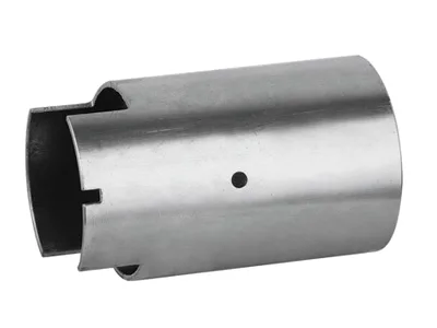
A cover that is really a boundary between fuel vapour and outside air
A fuel pump cover with fittings does not have one sealing job, it has two, and they pull in opposite directions. On the inside it has to keep the pump module and its vapour seal contained: fuel vapour escaping a cover is a smell problem, a hydrocarbon-emission problem and, in a well-vented design, a controlled vent rather than a leak at all. On the outside it has to keep water, road salt, pressure-wash fluid and stone chips out of the module bay. A cover designed only for the first is a vent; a cover designed only for the second builds a vacuum and pulls fuel across the module seal.
This is why deep-drawn fuel pump covers are drawn as an assembly of three separate decisions: the metal and its thickness, the seal lands that mate to the module and to the tank, and the fittings that pass fuel or electrical through the wall. We handle all three on the same part, drawn from coil or blank with in-process annealing so the walls thin evenly, and we hold +/-0.05 mm on formed features with capability data on the critical dimensions.
The vent is a design decision, not an omission
Every fuel system needs somewhere for the volume of vapour the module generates to go. The mainstream arrangements are:
| Vent to atmosphere through the module | The vapour line passes through the cover as a fitting, then runs to the canister or to the vent valve. The cover’s job is then to carry that line and to seal the pass-through; pressure management belongs to the valve. |
|---|---|
| Pressure/vacuum relief valve in the cover | The cover hosts a relief or shut-off valve so the module cannot be exposed to pressure cycling from the tank. This is common where the tank is underbody-mounted and exposed to pressure spikes from road impacts. |
| Sealed cover with a controlled leak path | Acceptable only where the vent line is small and the vapour volume is low. The cover must then define the leak path precisely, because a defined path is testable and an undefined gap is not. |
Whatever the arrangement, the vent fitting’s thread or its barb becomes the highest-cycle fatigue feature on the cover. Fuel systems see thousands of pressure and temperature cycles over a vehicle life, and the fitting is where that cycling enters a metal part. A drawn boss gives the fitting something to seal against and something to react into; a hole punched through a flat wall with a fitting screwed straight into the sheet is asking for the sheet to distort.
Seal land geometry is the whole game
A cover seals by geometry, and the geometry has to be made on a stamping, not on a lathe. The main land types you will see on these covers:
- Flange face seal. A flat drawn rim that compresses a O-ring against the tank flange. Simple and effective, but the flatness of that rim across the whole diameter is the controlling dimension – a rim that is high on one side will leak on that side at exactly the clamping load the module requires. This is why cover flatness gets measured on a surface plate or granite, not just with calipers.
- O-ring groove in the cover wall. Works when the cover telescopes into the module flange. The groove must be deep enough that the O-ring cannot bottom out before the flange has pulled down, and shallow enough that the O-ring is still compressed when the flange arrives. Groove depth tolerance is one of the tightest numbers on the part.
- Conical or flare seat. A drawn cone that a standard fitting or tube seat matches against. This is common where the cover also passes a fuel line, and it means the cover’s function depends on a tube seat coming from another supplier.
- Captured elastomer in a channel. The elastomer is part of the cover assembly, retained so it cannot displace during assembly. Good against assembly damage, at the cost of a more complex channel and a tighter control on elastomer compression.
The failure mode that recurs is not a bad material – it is seal compression inconsistent across the joint. That is a geometry problem before it is a tolerance problem, and it is worth asking the elastomer supplier for the compression range the design should hit, then designing the groove depth to the middle of that range rather than to its theoretical maximum.
Choosing the metal for the fuel side
Modern fuels are more aggressive than petrol of twenty years ago. Ethanol blends hold water, and that water is what attacks the metals and the elastomers. The grades we hold and their standing in this duty:
| SPCC / DC01 carbon steel | The volume choice for a structural cover. Stable against dry fuel and against ethanol blends within their rated water content. Needs coating for the exterior and a well-controlled surface inside – drawn and annealed steel carries drawing lubricant residue that must be removed before the cover goes into a fuel-wet cavity. |
|---|---|
| 304 stainless steel | Corrosion-resistant outside and inside; used where condensation and salt are the concern rather than the fuel itself. |
| 316 stainless steel | Where the cover sits in a splash zone or where chlorides are expected in the vapour path. |
| Aluminium | Light, easy to draw, good thermal conductivity for a cover near hot components. Needs a controlled surface finish – aluminium oxide skins readily and any retained lubricant becomes a corrosion site. Cannot be brazed with the same fillers as steel, which matters if fittings are attached in the shop. |
| Brass and copper | Used for the fitting bodies and for boss features, and sometimes for the whole cover where thermal conductivity drives the design. Both are excellent with fuel; both are subject to dezincification in brass, so the alloy grade matters in humid, wet service. |
Surface finish on these covers is plated, powder coated, anodised or polished per the print, and samples are approved in writing. The finish specification needs one extra line that people forget: whether the fuel-wetted surface is allowed any coating, plating or residue at all. If the answer is no, that has to be a written requirement on the drawing, because the default expectation when someone says “zinc plate” is the outside.
Draw depth, wall thinning and why annealing is on the invoice
A cover that reaches down to locate a pump module is a deep draw, and deep drawing is where the material decides whether the part is possible. The wall thins as the material is pulled around the punch radius, and the thinning is not uniform – it concentrates where the flow changes direction. In-process annealing between stages restores the ductility the previous stage consumed, which is why the process description on this part specifically calls it out.
The practical consequences for the drawing review:
- Corner radii are not cosmetic. Punch and die radii that are too small raise thinning at the shoulder and risk splitting. The review checks these before tooling, not after.
- Wall thickness tolerance is one-sided in practice. A cover will rarely be rejected for being slightly thick, and often will be for being thin, because the thin zone is where the stamping splits and where the sealing land loses stiffness.
- Annealing leaves a surface. Annealed surfaces carry an oxide skin. On a fuel-wet interior that oxide is a contaminant and a corrosion initiation site, so passivation or a controlled wash belongs in the route, and the cleanliness specification is a real requirement rather than a nicety.
- Deep draws are springy. A cover with substantial depth can distort in handling and in transit. Restrictive packaging and, for high-volume parts, a nesting-friendly shape are worth discussing at review.
Press capacity runs from 5-250 T mechanical to 250-500 T hydraulic. A cover of this class, with a deep draw plus a formed seal rim plus pierced fitting holes, is commonly a multi-stage job where the last stages run in hydraulic because of the tonnage required to form and size the rim without marking the fuel-wetted surface.
The fittings themselves
The fittings are the most common source of trouble on this part, because they arrive with their own tolerances and their own leak history. Four decisions to settle at quotation stage:
- Threaded or welded. A threaded fitting gives a serviceable joint but needs a boss that can hold the torque without stripping; a welded fitting gives a permanent, very reliable joint but puts a welding operation and its distortion into the route. If the fitting is welded, the cover’s material and thickness decide the process – steel and stainless steel weld readily, aluminium needs care and a filler that will not contaminate a fuel path.
- Sealing method. Parallel thread with a bonded seal, tapered thread with a compound, or a face seal against a boss – each puts a different height tolerance on the boss. The face-sealed boss is the tightest, and it is the one that most often causes trouble because thread engagement is no longer doing the location job.
- Inserted or machined boss. For a fitting that must be strong or leak-tight to a low number, a pressed-in or welded-in insert is more reliable than a thin drawn boss. Drawn bosses of 1.2 mm wall are perfectly adequate for low-pressure fuel return but not for a pressure test at the pump outlet.
- Who supplies the fitting. We can supply the fitting, or accept a nominated part from the customer. That choice changes the quotation and the schedule, and it changes who carries responsibility when a joint weeps in service – so it is worth being explicit about it in the order.
Verification and the paperwork that goes with it
For a part that separates fuel from atmosphere, the inspection plan is not decorative. We check first articles and batch samples on the CMM, and the dimensions worth reporting are the ones the seal depends on: seal land flatness, groove depth and width, fitting thread and its position, boss concentricity, and hole position for any attachment feature. Leak testing of the assembled cover is specified by the customer and is normally done on the module rather than on the bare cover.
Prototype and pre-production samples are provided against the drawing, the sample is retained as the master, and production starts only after your written sign-off. Repeat orders reuse the approved first article. We quote in USD or EUR, FOB Ningbo or Shanghai, payment by T/T or L/C. Send drawings, or send a sample to be measured; unusual walls, threads or tolerances get feasibility-checked first, and any revision is re-quoted once rather than quietly absorbed into the original price.
Drawing a cover like this is a chain of decisions — draw ratio, wall thinning, radii and trim. Our deep drawn covers design guide works through each of them with worked numbers.
Specifications
| Item | Deep Drawn Fuel Pump Cover with Fittings |
|---|---|
| Brand | AUNOV |
| Designing | Send drawings, or send a sample to be measured – unusual walls, threads or tolerances are feasibility-checked first; revisions are re-quoted once rather than silently absorbed. |
| Tooling | The die is dedicated to your part and maintained on a recorded schedule. |
| Samples | Prototype and pre-production samples are provided against the drawing, so the sample is retained as the master, and production starts only after your written sign-off. |
| Materials | Carbon steel (SPCC / DC01), 304 / 316 stainless steel, aluminium, brass and copper – the grade is matched to the duty of this fitting. |
| Surface finish | Plating, powder coating, anodising or polishing, per the print; alternatives quoted with the quotation, samples approved in writing. |
| Processing | Deep drawing from coil or blank, with in-process annealing so walls thin evenly; in-process checks sit between stages, not only at the end. |
| Equipment | Mechanical presses 5-250 T plus 250-500 T hydraulics, with in-line annealing, with in-house toolmaking to keep dies and fixtures maintained. |
| Tolerance | +/-0.05 mm on formed features, with capability data on critical dimensions; GD&T per drawing, PPAP-style reports on request. |
| Delivery terms | FOB Ningbo or Shanghai, payment by T/T or L/C, quoted in USD or EUR; repeat orders reuse the approved first article. |
Frequently Asked Questions
Why does a fuel pump cover have two sealing jobs?
On the inside it must contain the pump module and its vapour, which is an emission and vent question, and on the outside it must keep water, road salt, pressure-wash fluid and stone chips out of the module bay. A cover designed for only one of those either leaks vapour or builds a vacuum that pulls fuel across the module seal, so both are solved on the same part.
How are the fittings sealed through a fuel cover wall?
The fittings pass fuel or electrical through the drawn wall, located off the shell datum so they relate back to the rest of the part, and sealed on a prepared face or a fitted insert. Each penetration is verified because a fuel cover fails at a penetration long before the wall does.
Which metal is used for a deep drawn fuel pump cover?
Carbon steel, 304 and 316 stainless steel, aluminium and brass are all options, with the grade matched to the fuel side and the service life. Mill certificates accompany the first article, and material substitutes are proposed only with your written approval.
What tolerance holds the seal lands on a fuel pump cover?
Formed features are held to a few hundredths of a millimetre with capability data on the critical dimensions, and the seal lands that mate to the module and to the tank are the controlled features. The relationship is proved on the CMM at first article and carried in the dimensional report.
Related Products


Request a Quote for This Part
Send a drawing or sketch — get material advice, tooling cost and a per-piece price within 24 hours (working days).