

A shield is a simple part with a long requirement list
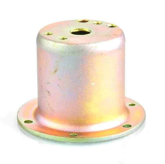
A deep drawn shield – the formed cover that protects a mechanism, blocks a spray, deflects heat, or keeps fingers and debris out – is one of the most common deep drawn parts and one of the most carelessly specified. The geometry is easy: a shell with maybe a flange and a few cut-outs. The difficulty is that a shield usually has to satisfy several requirements at once – mechanical protection, ingress protection, thermal behaviour, sometimes electrical continuity – and those requirements trade against each other in the wall thickness and the material.
We draw shields from 0.4-1.2 mm steel, stainless steel, or aluminium, and this page covers what a shield has to do, how each requirement pushes the design, and where the specification usually goes wrong.
What a shield is actually asked to do
Shields arrive with a mix of these functions, often without the drawing making clear which one dominates:
| Mechanical protection | Keeps impact, abrasion, or contact away from a mechanism. Needs stiffness and, if impacts are real, resistance to denting. |
|---|---|
| Ingress protection (IP) | Blocks dust and, sometimes, water spray. Needs a close fit at the mating surface and often a gasket or a labyrinth joint. |
| Thermal shielding | Deflects radiant heat. Favours a reflective, heat-resistant surface and, where radiant load is high, a standoff gap. |
| EMI shielding | Attenuates electromagnetic noise. Needs a conductive, magnetically permeable metal and, above all, continuous bonding. |
| Appearance | Visible shields are cosmetic parts; surface finish, edge quality, and flatness become functional requirements. |
The reason this list matters is that a shield optimised for one function is often poor for another: a thick steel shield is stiff and good for EMI but heavy and costly; a thin aluminium shield is light and reflects heat but shields EMI poorly and dents easily. We ask the customer to rank the functions rather than treat them as equally weighted.
Wall thickness and the trade it forces
Wall thickness is where most of the trade happens:
- Thin (0.4-0.6 mm) – light and cheap, adequate for a dust shield with light contact; dents in handling and provides little EMI attenuation.
- Medium (0.6-1.0 mm) – the working range for most protective shields; balances handling robustness, IP sealing pressure, and cost.
- Thick (1.0-1.2 mm and above) – for impact protection or meaningful EMI attenuation; heavier and, at some point, a candidate for replacement by a casting despite the weight.
Because stiffness scales with thickness cubed but weight scales linearly, a rib or a small dome in a thin shield usually beats a thicker wall for stiffness at equal weight. We propose those features before agreeing to thicken a shield.
Ingress protection: the joint is the part
An IP-rated shield is only as good as the joint where it meets the housing. Three designs cover most needs:
- Flanged lap with a gasket – the shield flange presses a gasket against the housing face; the flange must be flat within a tolerance that lets the gasket compress evenly, typically 0.1-0.2 mm across the seal.
- Labyrinth (no gasket) – a formed groove and a matching rib create a tortuous path that stops spray without a soft seal; robust at temperature and vibration, but must be designed as a pair with the housing.
- Interference rim – a slightly oversized rim presses into a groove; simple, but only where the shield is not removed in service.
We hold the flange flatness and the rim diameter as controlled features and can supply a matching housing feature scheme so the seal is designed as a system rather than improvised at assembly.
Heat deflection: geometry as much as material
A heat shield works in two ways – reflection and standoff. Reflection comes from a bright or aluminised surface; standoff comes from holding the shield away from the protected part so the air gap insulates. A drawn shield with a formed standoff rib or a stepped profile creates that gap without a separate spacer, which is a common way to get real thermal benefit from a single drawn part. Material choice (stainless steel or aluminised steel) then handles the temperature of the shield itself.
Edges, cut-outs and the safety detail
Shields are handled by people, so edge condition is a real requirement, not a nicety. A sheared edge from a trim die carries a burr that cuts; we specify a deburr or a rolled edge on any exposed rim. Cut-outs for cables, access, or airflow need the same treatment, and where a cut-out pierces a shield with an EMI function, its size is a functional dimension and not a rough one.
Our deepest drawn shields reach 150 mm and 80 mm deep
- Diameter: 15-150 mm.
- Depth: 5-80 mm.
- Wall: 0.4-1.2 mm.
- Features: flange, rim, standoff ribs, beads, cut-outs, formed standoffs, mounting tabs.
A rolled or hemmed edge, and the burr it removes
Can you make a shield with a rolled edge? Yes – a rolled or hemmed edge both removes the burr and stiffens the rim, and it is a low-cost die feature.
Will a drawn shield be flat enough for an IP seal? The flange flatness we can hold is normally sufficient for a gasket seal; where the sealing face is large or the gasket is thin, we will discuss a sizing step.
Do I need stainless steel for a heat shield? Only if the shield itself gets hot; aluminised steel reflects radiant heat at lower cost if the shield stays cooler than the coating’s limit.
Can the shield double as a structural mount? Yes, where the wall and any ribs give it the stiffness; we will size it for the load rather than let the mounting loads dictate a heavy wall everywhere.
Specifying a deep drawn shield
Send the primary function (and the secondary ones, ranked), the mating surface and any seal requirement, the temperature and any electrical requirement, the cut-outs that are functionally required, the exposed edges, and the annual volume. Those inputs settle material, wall, flange scheme, and features – which is what stops a shield from being over-built for the wrong requirement and under-built for the one that matters.
Not sure whether to draw, machine or weld this geometry? The guide to deep drawn covers compares the three routes and shows where each one wins; the full Precision Deep Drawn Parts range is linked from the overview page.
Specifications
| Item | Deep drawn shield |
|---|---|
| Brand | AUNOV |
| Designing | Send drawings, or send a sample to be measured – samples are reverse-measured into a controlled drawing; the same drawing is used for every repeat order. |
| Tooling | The tooling record travels with the part number, so maintenance history is never lost. |
| Samples | Samples are issued for approval before the run, so the approved first article becomes the gauge reference, and the signed sample is kept for future reorders. |
| Materials | Carbon steel, 304 / 316 stainless steel, aluminium and brass are all held in stock; the final grade is fixed with the drawing review. |
| Surface finish | Plating, powder coating, anodising or polishing, per the print; masking and laser marking available where needed. |
| Processing | Deep drawing on maintained presses, blank size and lubrication logged per run; in-process checks sit between stages, not only at the end. |
| Equipment | Mechanical presses 5-250 T plus 250-500 T hydraulics, with in-line annealing, backed by CNC turning centres and a climate-controlled inspection room. |
| Tolerance | +/-0.05 mm to +/-0.1 mm across the part, wall thickness held to print; capability is checked on the first article before the run continues. |
| Delivery terms | Order ships FOB unless you prefer DDP; payment by T/T or L/C, freight quoted to destination. |
Frequently Asked Questions
Is this a spray guard, a heat guard, or a finger guard – and does the answer change the drawing?
It changes almost everything downstream. A spray guard is judged by whether fluid can reach what is underneath, so coverage, drip edge and the position of any opening matter more than strength. A heat guard is judged by whether heat is deflected while air can still move, which usually means a stand-off gap rather than a thicker wall, since metal conducts well and a guard pressed tight against a hot part simply becomes a heat bridge. A finger or ingress guard is judged by whether a probe of a defined size can reach a hazard, which sets opening size and edge distance instead. All three are called a shield, so if the drawing does not say which one governs, the supplier is left to guess.
Why does a heat guard usually gain more from an air gap than from extra thickness?
Because conduction along a continuous metal path moves heat faster than radiation across a small gap stops it. Adding material makes the guard hotter and heavier without necessarily making the protected part cooler, while lifting the guard clear on stand-offs or beads and letting air pass behind it interrupts the path instead. That is why these covers are drawn from light material in the 0.4-1.2 mm range rather than from something heavy, and why the stand-off feature is specified as carefully as the shell itself.
When does the cut edge stop being a detail and become a requirement?
As soon as hands or cables can reach it, which is often. A sheared edge on thin material is sharp enough to cut, and it sits exactly where people work during assembly and service. Rolling or hemming the edge costs trim height that has to be left above the trim line, but it removes the hazard, closes the edge against corrosion creep and stiffens the mouth of the shell at the same time. Where a hem cannot be accommodated, deburring and a defined edge break are the minimum, and both belong on the print rather than in a note to the shop.
At 15-150 mm across and up to 80 mm deep, can a shield be drawn in one operation?
Sometimes, but depth alone does not decide it. In this range the combination of plan size and depth sets whether a single draw still leaves a usable wall, and the deeper shields usually need staging with interstage annealing so thinning stays even and the corners do not tear. Wall thickness is held to the drawing rather than being whatever the press happens to deliver, which is why bringing the draw stages into the drawing review is what makes 80 mm practical on a shell this size.
Related Products



Request a Quote for This Part
Send a drawing or sketch — get material advice, tooling cost and a per-piece price within 24 hours (working days).