
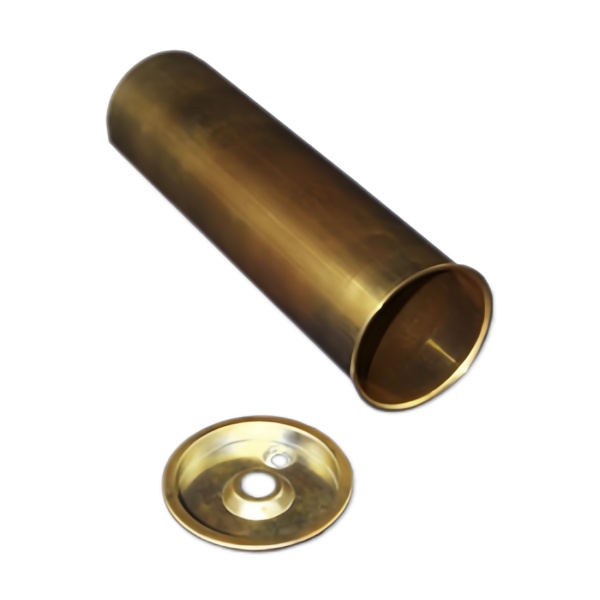
Two processes, one part, and the joint is the design
This part is a drawn brass tube with a stamped disc closing one end. It arrives at the drawing board looking like a simple assembly, and the four or five lines describing the tube and the disc are usually the easy lines. The engineering content sits in the join between them. A tube has a wall that has been thinned by drawing and carries the residual stress of that process; a stamped disc has a blanked edge with a roll over direction and a burr side; and however the two are brought together, the joint has to hold against whatever the part is for, whether that is pressure, a vacuum, a temperature cycle or simply a customer who will drop it on a floor.
The useful starting point is to ask what the joint has to guarantee. Three answers are common, and they lead to different processes. If the joint has to guarantee nothing but retention, a light press and a stake will do. If it has to guarantee a seal against pressure, the process is soldering or brazing, and the joint geometry, the flux and the cleanliness become the whole discussion. If it has to guarantee a position, the disc becomes a locating feature and the tube becomes the datum, which reverses the tolerance logic. Deciding which of the three applies before choosing a process is what stops the assembly from being expensive for the wrong reason.
The tube: drawn brass and the temper you asked for
Brass draws beautifully, which is exactly why it is easy to specify a temper that cannot survive the forming operation or, worse, a temper that survives forming and then fails in service. The common grades in this class are the two-phase brasses around H62 and the single-phase grades near H65, and the difference is not cosmetic. H65 and the higher copper grades are single phase, ductile, take severe drawing and are easy to solder. H62 and the grades nearer the middle of the two-phase field are stronger and machine better but draw less deeply before they need an anneal.
Temper is specified through the supply condition, and the practical states are soft annealed, half hard and hard. A drawn tube in the soft state will form and then be soft, which is correct for a part that will be flared, beaded or crimped afterwards and wrong for a part that has to carry pressure. A half hard tube resists pressure and distorts less during the jointing operation, at the cost of a shorter forming window for any secondary operation such as flaring the open end. The honest way to write this on a drawing is to state the temper with the mechanical property range it implies, not only the temper name, because the name is interpreted differently between mills.
- Single-phase grades near H65: best for severe drawing and for soldering.
- Two-phase grades near H62: stronger, better machining, more annealing between draws.
- Supply condition soft, half hard or hard, with a property range rather than only a name.
- Wall thickness as a range, with a minimum figure the joint can rely on.
The end disc: stamped, coined, and the direction of the burr
The disc is normally blanked from strip and, where flatness matters, coined or lightly embossed in a second hit. Two of its properties decide how it behaves in the joint. The first is flatness. A disc that cups slightly will contact the tube on one side when pressed in, and the joint will be tight in one place and open in another. Coining a shallow ring into the disc, or a shallow dome, gives it a defined and repeatable shape, and that is easier to control than trying to blank a perfectly flat disc out of strip that has its own internal stress.
The second property is the direction of the blanking burr, which is a functional decision rather than a housekeeping detail. If the disc is pressed into the tube with the burr leading, the burr acts as a scraping edge; it shaves the bore, produces loose brass particles inside the assembly and makes the insertion force unpredictable. Burr trailing gives a cleaner press and a more repeatable force but leaves the sharp edge on the outside where it can be a handling and a plating concern. For a soldered or brazed joint the burr should face away from the joint so that the capillary gap is not disturbed by a raised edge, and the burr direction should be written on the drawing as a note, because the toolmaker will otherwise choose whichever way is easier to strip.
Four ways to close the end, and what each one guarantees
The end can be closed in several ways, and each one buys a different set of guarantees. Choosing on the basis of cost alone usually means choosing the one that guarantees the least, and then being surprised when the part leaks.
- Press and stake. The disc is pressed to a shoulder and the tube wall is deformed into a groove or over the disc in three or four places. Fast, cheap, no heat. It guarantees retention and a mechanical stop, and it guarantees nothing at all about sealing unless an elastomer is captured at the same time.
- Press with a sealing compound. An anaerobic or epoxy compound is applied before pressing and cures in the joint. It gives a usable seal for low pressure, and its reliability depends almost entirely on the cleanliness and the gap of the joint, both of which have to be specified.
- Soft soldering. The joint is filled with a tin based solder at 180 to 250 degrees Celsius. It seals, it is relatively easy to inspect, and it is the usual choice for brass. The risk is flux residue: a chloride flux left inside a sealed volume will corrode the wall from the inside, and cleaning has to be specified as part of the process rather than as a good intention.
- Brazing. A filler at 600 to 900 degrees Celsius gives a much stronger joint than soldering, at the price of a heat cycle that will anneal the tube, oxidise the surface and potentially distort the disc. Wherever brazing is chosen, the drawing should say what the part is allowed to look like afterwards, because the tube will not be in the same metallurgical state it was before.
One further variant deserves a mention because it is often the best answer: form the end closed instead of joining a disc to it. A drawn brass tube can be closed by a subsequent drawing or nosing operation, which produces a seamless closed end with no joint at all. It becomes uneconomic when the closed end has to be thick, when the tube is very long relative to its diameter, or when the end disc is a different material. Where none of those apply, the seamless option removes the entire joint discussion from the drawing.
The joint is the leak path
If the assembly is meant to hold anything, the leak will be found at the joint, and it will be found at the specific place where the gap between the disc and the tube is largest. That gap is set by the tube’s internal diameter, which is a drawn dimension with the ovality and the wall variation of the draw, and by the disc’s outside diameter, which is a blanked dimension with its own variation. Both are ordinary tolerances, and their arithmetic is not reassuring. A tube bore of 20.0 plus or minus 0.1 mm and a disc at 19.9 plus or minus 0.05 mm can produce a diametral gap anywhere between 0.0 and 0.25 mm, and the joint has to work at the top of that range as well as at the tight end.
Two practices make the joint predictable. The first is to add a shoulder, a step or a bead inside the tube so that the disc lands on a defined axial face and the radial gap is set by a machined or coined feature rather than by two loose tolerances. The second is to specify the gap that the jointing process needs. A soldered capillary joint wants a specific clearance, typically 0.05 to 0.15 mm on diameter depending on the filler, and if the drawing does not enforce it the joint will be tight in some batches and loose in others, with seal quality following. Both practices cost a little tooling and remove a class of failure that is otherwise found only in the field.
How we verify a brass tube with a stamped end disc before it ships
Verification on this part is dominated by the end joint, because that is where brass tubes fail – not in the wall. The first article is sectioned to prove the joint; production joints are tested by a defined leak or proof method rather than by appearance.
- Section the first-article joint and measure the bond or seam width and any void at the disc edge; a visible gap is a leak path, not a cosmetic mark.
- Pressure or vacuum test a defined fraction of production at the rated level with a bubble or decay acceptance.
- Ultrasonic wall check at the thinnest drawn region and at the disc transition.
- Dimensional check of the tube OD, the disc face and any machined feature against the print.
- Surface and cleanliness inspection for flux residue or tarnish that would compromise a later finish or solder.
- File the section report, leak-test record and material certificate under the part number.
Choosing between drawing, machining and welding comes down to the shape of the part: the guide to deep drawn covers sets out where each route wins, and the overview page links through to the full Precision Deep Drawn Parts range.
Specifications
| Item | Brass Deep Drawn Tube with Stamped End Disc |
|---|---|
| Brand | AUNOV |
| Designing | Send us your 2D drawing, or mail a sample for measurement, a manufacturability review comes back with the quotation. |
| Tooling | Dies designed and built in our own toolroom, with your part number on the tool record. |
| Samples | Approval samples ship with a full dimensional report and material certification. |
| Materials | Brass leads the stock list for this part, alongside carbon steel (SPCC / DC01), 304 / 316 stainless steel, aluminium and copper, per the drawing. |
| Surface finish | Plating, e-coat, powder coating, anodising or passivation, exactly as your print calls for. |
| Processing | The draw sequence is staged, with in-line annealing wherever the draw ratio requires; piercing and CNC machining are done in house. |
| Equipment | Press capacity from 5 to 500 T across mechanical and hydraulic lines, CNC cells plus a temperature-controlled CMM room. |
| Tolerance | As-drawn tolerance +/-0.1 mm, +/-0.03 mm on machined surfaces. |
| Delivery terms | Prices FOB, with DDP for EU and US on request, payment T/T or L/C, D/P for repeat accounts, call-off scheduling supported. |
Frequently Asked Questions
Why is the joint the real design on a tube with an end disc?
The tube wall is thinned by drawing and carries residual stress; the stamped disc has a blanked edge with a burr side. However they join, the joint must hold against pressure, vacuum, temperature cycling or a drop, so the joint – not the two parts – is where the engineering sits.
What does the end disc closing process have to guarantee?
Retention alone needs only a light press and stake; a pressure seal needs soldering or brazing where joint geometry, flux and cleanliness become the whole discussion; position needs the disc as a locating feature with the tube as datum. The requirement is fixed before the process.
Which brass and temper are used for the tube?
The drawn brass tube is produced to the temper specified on the drawing, with the disc stamped and coined; the burr direction of the disc is controlled so it faces away from the seal.
How is a brass tube with end disc quoted and verified?
The joint is verified for leak path and position, with first-article and batch inspection. The typical minimum order is 1,000 pieces with a 24-hour quotation.
Related Products


Request a Quote for This Part
Send a drawing or sketch — get material advice, tooling cost and a per-piece price within 24 hours (working days).