
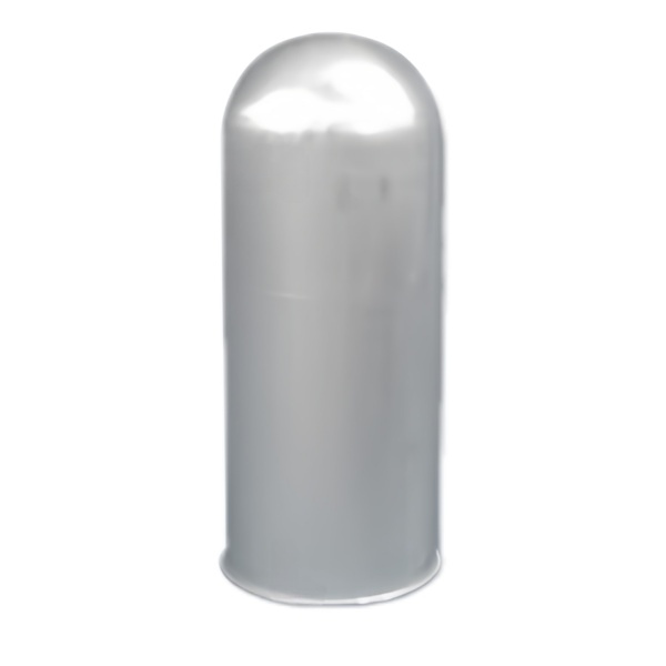
The Aluminum Deep Drawn Dome End Cylinder Shell puts a hemispherical or elliptical closure on a drawn tube wall, and the shape carries load the flat bottom cannot. This page sets out the apex thinning arithmetic, the blend radius that decides fatigue life, and the checks we run on every dome shell lot.
Dome ends carry pressure by shape, not by wall thickness alone
A flat drawn bottom holds pressure only by bending, which is why flat-bottom cans burst at a fraction of the pressure of a comparable domed shell. A dome puts the entire wall into membrane tension – the same material working as a chain in pure pull instead of a plate in bending – and the payoff is large: a 1.0 mm hemispherical dome on a 70 mm diameter shell sustains internal pressures that would bulge a 1.5 mm flat bottom. Customers specify dome ends for pressure cycles, vacuum service, and impact energy absorption for exactly this reason.
The consequence for the drawing floor is that dome geometry is a strength dimension, not a cosmetic one. We control apex height to +/-0.5 mm and dome profile against a template or CMM curve, because a dome that is 10 percent shallower than drawn intent has measurably less meridional stiffness even though every gauge dimension on a flat drawing still passes. That is why our first-article reports include a profile trace, not just diameter and depth figures.
Apex thinning: the number every dome shell drawing should state
When a flat blank is pushed into a dome, the center travels farthest and thins the most. On a hemispherical dome the apex can lose 8 to 12 percent of blank thickness in a single-stage draw; on deep elliptical domes drawn in multiple stages, cumulative thinning of 15 percent is routine. The drawing that matters is not the finished shell but the blank – and if the customer needs 1.0 mm minimum at the apex in service, the blank must start at 1.15 to 1.2 mm, with the whole process scheduled around landing that number.
We state apex thickness explicitly on the manufacturability review and measure it ultrasonically at eight points on the dome of the first article. Two failure modes dominate when this is left implicit: tearing at the apex when the blank is too thin for the profile, and “thick-apex” shells that pass pressure test but fail later at the blend radius, where the abrupt thickness step concentrates bending. Both are schedule problems, not material problems – a two-stage draw with an intermediate anneal at 360 degrees C typically lands apex thinning inside 8 percent where a single aggressive hit loses 15.
Blend radius between dome and wall, and the fatigue line it creates
Load never stays in the dome; it transitions into the cylindrical wall across the blend radius, and that transition is where pressure-cycled shells crack. A blend radius of 5 percent of diameter or larger spreads the bending so the stress transition is gentle; radii under 3 percent of diameter create a knee that behaves like a hinge, and every pressure cycle flexes the same narrow band of metal until it work-hardens and cracks. Fatigue failures on dome shells almost never originate at the apex – they originate at the blend, and theSEM photographs we collect on development parts confirm it every time.
Our rule of thumb on the review is a minimum blend of 0.08 times the shell diameter for static pressure and 0.12 times diameter for cycling service. The die is built with the blend on a machined insert that can be re-cut as it polishes in, because the radius is the fastest-wearing feature in the tool – after 20,000 hits the blend typically grows 0.3 to 0.5 mm from burnishing, and we re-set it rather than let the fatigue-critical dimension drift.
3003 or 5052 for a dome shell, decided by the pressure cycle
3003 is the default body alloy because it draws deep domes in fewer stages – its wider window tolerates the high strain at the apex without intermediate annealing in many cases. But 3003 at 130 MPa yield is the wrong choice for a shell that cycles: fatigue at the blend radius is governed by strain amplitude, and the lower-strength alloy accumulates damage faster. 5052-H32 at roughly 195 MPa yield extends cycle life by the same ratio in the high-cycle regime, and its cost is a narrower draw window and visible springback – typically 1.5 to 3 degrees of diameter recovery after dome forming, which we compensate in the die.
There is a third path for shells that need both drawability and fatigue life: draw in 5052-O (fully annealed) and age or partially stabilize after forming. The formed shell then holds its geometry better than H32 drawn in one shot, at the cost of one more furnace pass. On pressure vessels this is usually worth it; on cosmetic or static-load shells it is money spent for nothing.
Spinning versus deep drawing for shallow versus deep domes
Not every dome should be drawn. Below about 0.25 draw depth to diameter, metal spinning from a pre-form or even from tube stock is often cheaper: tooling is a single mandrel, and wall thickness is controlled directly by the roller rather than by blank budget arithmetic. The trade is cycle time – spinning is minutes per part where deep drawing is strokes per minute – so quantities above roughly 2,000 pieces usually push back toward drawing. Above 0.4 depth to diameter, drawing wins outright, because spinning deep domes thins the wall unpredictably near the mandrel nose.
We run both processes on the same floor and quote the cross-over honestly. When a customer’s dome sits near the boundary, the decision inputs we ask for are annual quantity, apex thickness tolerance, and whether the shell will be welded or brazed downstream – spinning leaves no flange trim scrap, but drawing leaves a trimmed flange that can serve as a weld land for free.
How we verify dome shells before they ship
- Trace the full dome profile on the CMM or against a calibrated template, checking apex height within +/-0.5 mm and profile deviation inside 0.4 mm at the blend.
- Measure wall thickness at the apex, the blend, and mid-wall with an ultrasonic gauge, eight points per sampled part, with apex minimum enforced per drawing.
- Verify the blend radius on sectioned first-article parts and confirm no thickness step above 0.1 mm across the transition band.
- Proof-test pressure-rated shells at 1.5 times working pressure, holding five minutes, with any permanent bulge over 0.2 mm cause for lot rejection.
- Confirm surface condition – no wrinkle folds in the flange zone, no draw lines deeper than 0.05 mm on sealing or fatigue-critical surfaces.
- File profile trace, thickness map, pressure record, and material certificate under your part number so repeat lots inherit the same verified schedule.
On tooling, a dome-end shell is a two- to three-insert job – the body draw, the dome reverse-draw, and the trim – and we build all of them in our own toolroom and hold them under your part number. Because the dome is the riskiest feature, we prove it on the first article before committing to a production run, and the pole-wall map from that first piece becomes the reference for every reorder. A programme measured in the low thousands pays the die back quickly; below a few hundred pieces we will usually suggest a fabricated or spun alternative and say so, because a drawn dome only wins on unit cost once the tooling is amortised.
For design changes after the first article, the cheap change is almost always a dimensional one – a longer body, a different mouth trim, a thicker pole – because it reuses the dome insert. The expensive change is a different dome radius or a different apex geometry, which means a new nose punch and a re-proven pole map. We flag which changes are tool changes and which are setting changes on the quotation so you can plan a derivative family around one dome insert instead of paying for several.
The engineering calls behind a part like this — draw ratio, wall thinning, radii and trim — each get worked examples in our deep drawn covers guide; the Precision Deep Drawn Parts pages gather the rest of the family.
Specifications
| Item | Aluminum Deep Drawn Dome End Cylinder Shell |
|---|---|
| Brand | AUNOV |
| Designing | Send us your 2D drawing, or mail a sample for measurement, our engineers reply with a manufacturability assessment and pricing. |
| Tooling | Every die designed and built in our toolroom, held and maintained under your part number. |
| Samples | Pre-production samples ship with a dimensional report and material certification. |
| Materials | Aluminium leads the stock list for this part, alongside carbon steel (SPCC / DC01), 304 / 316 stainless steel, brass and copper, per the drawing. |
| Surface finish | Plating, e-coat, powder coating, anodising or passivation as the drawing calls out, as called out on your print. |
| Processing | Progressive deep draw stages with in-line annealing as the draw ratio demands, then pierced and CNC-machined in house. |
| Equipment | Mechanical presses 5-250 T, hydraulic presses 250-500 T, in-house CNC cells and a temperature-controlled inspection room. |
| Tolerance | Drawn tolerances held to +/-0.1 mm, machined features held to +/-0.03 mm. |
| Delivery terms | FOB standard, DDP offered for EU and US, T/T and L/C; D/P on repeat accounts, call-off schedules supported. |
Frequently Asked Questions
Why does a domed end hold so much more pressure than a flat drawn bottom?
A flat drawn bottom resists pressure by bending, which is inefficient, while a dome puts the whole wall into membrane tension – the same material working as a tie in pure pull rather than as a plate in bending. That is why a flat-bottom can bursts at a fraction of the pressure of a comparable domed shell.
What should every dome shell drawing state that most leave out?
Apex thinning. The top of the dome is where the metal has travelled furthest and thinned most, and because it also happens to be where stress concentrates, leaving it unstated means the thinnest part of the pressure boundary is the undocumented one.
Why does the blend radius between dome and wall matter so much?
It is both a stress reliever and a fatigue line. Opened generously it spreads the transition between two different stress states; too tight and every pressure cycle works that line as though it were a crack waiting to start. It is worth specifying rather than leaving to whatever the tooling produces.
Drawn or spun for this geometry?
It follows depth. Spinning is efficient for shallow forms and can be economical at low volume because tooling is light, while drawing takes over as the dome gets deeper and the wall has to be controlled. The crossover depends on the profile rather than on a rule of thumb, so both are quoted against the drawing.
Related Products


Request a Quote for This Part
Send a drawing or sketch — get material advice, tooling cost and a per-piece price within 24 hours (working days).