
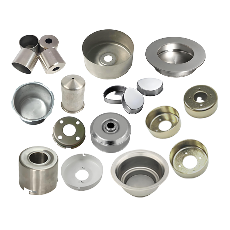
The Assorted Deep Drawn Cups Caps and Flange Bodies group three geometries that share our presses, our material stock and our inspection room, but not their process plans: caps that form in a single hit, cups of moderate depth that need one or two draw stages, and flange bodies where the formed flange carries the fastener pattern and the sealing surface. They are shown together because buyers often quote all three as “deep drawn parts” and then find that the tooling arithmetic, the cycle time and the failure modes are different for each. This page sets out those differences family by family, so the quotation you receive for each can be judged on its own engineering rather than on a category label.
Caps, cups and flange bodies share a press but not a stage plan
A cap is, in drawing terms, a shallow deformation: depth less than roughly a quarter of the blank diameter, corner radius generous, and the draw ratio — blank diameter over punch diameter — sitting under about 1.2. At that ratio the material flows into the die with little assistance, one press stroke finishes the shape, and the engineering effort goes into edge quality after trim and into keeping the flange or rim flat. The failure mode is rarely a crack; it is a rim that waves after trimming because residual stress from an uneven blank holder releases when the trim removes the constraint.
A cup at draw ratio 1.6 to 1.8 is the textbook case: the limit drawing ratio for annealed SPCC sits near 1.9 to 2.0, so a single-stage cup is comfortable, but the wall thins measurably at the punch nose — typically 8 to 12 percent at the critical tangential section — and that thinning is documented on the first article so downstream machining knows what it is cutting into. Cups beyond a ratio of about 2.0 are staged: first draw to an intermediate diameter, then a second and sometimes a third reduction of roughly 25 to 30 percent each, with in-line annealing between stages where the material has work hardened past its remaining ductility.
A flange body is drawn for the flange as much as for the shell. The flange is the functional surface: it carries bolts, seats a gasket, or locates into the next assembly. That changes the process priority from flow control to flatness and planarity — a flange that cups or twists by half a millimetre is a rejected part even when every diameter is in tolerance, because the bolt pattern will not pull it flat without distorting the shell below it.
The draw ratio ladder decides tooling cost before anything else
When a new part number enters quotation, the first calculation is the ratio ladder: how many draw stages from the blank to the finished shell, and where the anneals fall. The ladder is what tooling cost is made of. A one-stage cap needs one draw die and one trim die. A two-stage cup needs two draw dies, the intermediate one sized so its shell can enter the second die with clearance for lubricant but without slack that would let it wrinkle. A three-stage deep shell adds an anneal cycle and the handling between stages, which is process time that shows up in the unit price long after the tooling is amortised.
We quote the ladder openly because it is the honest driver of both numbers. If a drawing permits a slightly larger corner radius at the shell bottom, a part can drop from three stages to two, and the piece price falls by a step change rather than a percentage. That trade — radius against stage count — is the single most common manufacturability recommendation we make, and it costs nothing to ask for at the review stage.
The ladder also decides press assignment. Mechanical presses from 5 to 250 ton run the shallow and moderate families at speed; hydraulic presses from 250 to 500 ton run the deep staged shells, where the slower ram speed and full-stroke force control keep the wall thinning inside the plan instead of letting it crack at the nose radius.
Flange width and the wrinkles that wait inside it
The flange is where a draw stores its trouble. As the blank holder closes, the flange region is compressed circumferentially as material flows inward; if the blank holder force is too low for the flange width, that compression buckles into wrinkles. Wide flanges on thin material — a 40 mm flange on 1.0 mm SPCC, for example — are the classic case, and they are managed with draw beads in the die face that locally increase the restraint, or with a double-action press where the blank holder force is set independently of the punch force.
The counter-failure is just as fatal: blank holder force too high, and the flange cannot feed, so the wall stretches instead of drawing and tears at the punch radius. Between wrinkle and tear there is a working window, and it is found at first article, recorded as press settings against the part number, and reused on every production run. That is the practical meaning of our process records: the window does not have to be found twice.
Flange bodies add one more constraint: the trimming operation that squares the flange also relieves its residual stress, which is why we trim after drawing rather than blanking to near-net flange width and hoping the draw leaves the flange usable. A trimmed flange is a stable flange, and stability is what the bolt pattern needs.
Trim, restrike and pierce: the sequence each family runs
After the last draw, every family goes through a defined finishing route. Trimming removes the irregular rim that drawing leaves — on cups, the rim carries the earing pattern of the mill’s rolling direction, four low spots and four high spots in rolled sheet, and the trim die is sized so the lows still clean up to the drawing’s minimum height. Restrike, where the drawing calls for it, re-seats the shell in a die with the final corner geometry, trading a few percent of additional wall thinning for a sharp, repeatable radius and a rounder shell. Piercing comes last among the forming operations: holes pierced before a subsequent draw stage wander as material flows, so unless the drawing is dimensioned from the pierced hole deliberately, we pierce after the shell is final.
For caps, the route is short — draw, trim, pierce if there are vent or fastener holes, and the part is done. For cups with a machined feature, the route extends into CNC turning: a spigot turned on the open end, a bore reamed to fit, or a groove cut for a retaining ring, all referenced from the drawn shell’s OD so the machined feature stays concentric to the drawn body. For flange bodies, the route ends with the flange: trimmed flat, pierced for the bolt pattern in one stroke so hole-to-hole position is die-controlled, and inspected for planarity against the surface plate.
Machined features hold +/-0.03 mm; as-drawn surfaces hold +/-0.1 mm. The drawing’s datums decide which regime each feature lives in, and we review that split with you before the first article, because moving a dimension from the drawn column to the machined column is the second most common cost decision on these parts, after the stage ladder.
How we verify cups, caps and flange bodies against the first article
Every family ships under the same discipline: the first article is measured in full on the CMM in our climate-controlled room, and every production batch is gauged back to it under the agreed sampling plan. The checks below are the ones that actually reject parts.
- Wall thickness at the thin band above the punch nose radius, ultrasonically or by section on the first article, with the reading archived against the part number so thinning drift is visible batch to batch.
- Rim or flange flatness on the surface plate with feeler gauges, cap family and flange body family alike, against the flatness band on the drawing.
- Diameters at the open end and at the shell mid-height, because drawn shells oval slightly in trim; the drawing states which diameter is functional and that is the one gauged on every batch.
- Hole-pattern position on pierced features against the die-controlled first article, with the pattern checked as position to datums rather than as individual hole sizes.
- Height after trim at four positions, catching earing that the trim could not fully absorb.
- Material identity against the mill certificate of the heat actually consumed, so the certificate in the shipment packet traces to the parts in the box.
- Surface condition at the rim and flange edges — no cracks at trim, no burr beyond the specified height, and no tooling pickup on the drawn wall.
Send the drawing — or a sample part to measure — and the quotation returns with the stage ladder written out, the features we recommend moving between drawn and machined tolerance regimes, and the tooling cost shown as its own line. The first article then ships with its dimensional report and material certificate, and the process settings are archived against your part number so the second batch is a repeat, not a retune.
If you are weighing drawing against machining or welding for this geometry, the guide to deep drawn covers sets out where each route wins; the full Precision Deep Drawn Parts range is linked from the overview page.
Specifications
| Item | Assorted Deep Drawn Cups Caps and Flange Bodies |
|---|---|
| Brand | AUNOV |
| Designing | Send us your 2D drawing, or mail a sample for measurement, a manufacturability review comes back with the quotation. |
| Tooling | Our own toolroom designs and builds every die, held and maintained under your part number. |
| Samples | First articles go out with a dimensional report and material certificate. |
| Materials | The stock list runs carbon steel (SPCC / DC01), 304 / 316 stainless steel, aluminium, brass and copper, with the final grade confirmed at the drawing review. |
| Surface finish | Plating, e-coat, powder coating, anodising or passivation as the drawing calls out, per the drawing. |
| Processing | Staged deep drawing, with in-line annealing where the draw ratio requires, pierced and machined on the same floor. |
| Equipment | Press capacity from 5 to 500 T across mechanical and hydraulic lines, in-house CNC cells and a temperature-controlled inspection room. |
| Tolerance | Expect +/-0.1 mm as drawn and +/-0.03 mm where surfaces are machined. |
| Delivery terms | FOB as standard, DDP available for EU and US destinations, T/T and L/C accepted, D/P for established customers, call-off schedules and blanket orders supported. |
Frequently Asked Questions
How does the draw ratio decide tooling cost across a family?
A cap sits under about 1.2 draw ratio and finishes in one stroke; a cup near 1.6 to 1.8 is the textbook single-stage case; anything past about 2.0 is staged with 25 to 30 percent reductions and in-line annealing. The ladder sets how many tools the family needs before any shape is cut.
Why do flange-width wrinkles appear after trim?
Residual stress from an uneven blank holder releases when the trim removes its constraint, so the rim waves. The flange width and trim sequence are planned so the rim stays flat rather than left to chance after cutting.
What does the first article document on a cup?
Wall thinning at the punch nose, typically 8 to 12 percent at the critical section, is documented so downstream machining knows what it is cutting into. Flange and rim are held to +/-0.05 mm with the wall controlled by the draw.
How are cups, caps and flange bodies verified?
Each family runs its trim, restrike and pierce sequence and is checked against the first article. The typical minimum order is 1,000 pieces with a 24-hour quotation.
Related Products


Request a Quote for This Part
Send a drawing or sketch — get material advice, tooling cost and a per-piece price within 24 hours (working days).