
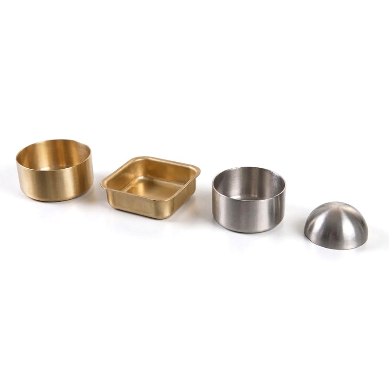
Box shells are not round shells: corner metal flow is the difficulty
A rectangular or box-shaped drawn shell is not a round cup with corners; it is a fundamentally harder forming problem wearing a similar shape. In a round draw, metal flows in from the flange uniformly – every point on the blank edge moves inward the same way, and the die controls one radius. In a box draw, the straight walls and the corners pull metal at completely different rates: the straight edge sections behave like simple bends, feeding metal easily, while each corner is a quarter of a deep draw – radial drawing with severe circumferential compression – that resists flow and works the material much harder.
The consequences are specific and predictable. Corner thinning: the punch nose at each corner stretches metal biaxially, and corner walls run thinner than straight walls on the same shell – 10 to 20 percent thinner is common without countermeasures, and the corner is where every box shell eventually tears if the draw ratio is pushed. Corner wrinkling: the flange material feeding a corner is compressed circumferentially as it converges, and without enough local binder force it wrinkles – wrinkles that get ironed into the wall as visible and structural defects.
Blank shape and corner relief in rectangular draw tooling
Tooling for box shells concentrates almost all its engineering in the four corners, and the choices are geometric before they are metallurgical. Corner radius on the punch is the governing dimension: a box corner radius below about 3 to 4 times sheet thickness is a tool-life and tearing problem in the first draw, and depth of draw beyond roughly half the corner-to-corner width demands staged draws with interstage anneals for the corners even when the straight walls would have managed in one. Our box-draw tooling practice, where the decisions actually live:
- Draw beads on the straight edges only, or heavier there. The straight sections feed too easily; local beads or a stepped binder brake them so the flange feeds at a rate matched to the corners. Without this, the straight walls over-draw while the corners starve – the shell balloons or the corners tear at the nose.
- Generous die entry radii at the corners to reduce corner drawing resistance, stepped down across draw stages rather than all at once.
- Blank corner relief: trimmed-back or notched blank corners, developed empirically on first articles until wall height is uniform – we measure height at corner, quarter-point and mid-wall until the rim runs level within the trim allowance.
- Stage planning around corner ductility: the reduction per stage at the corners is what limits a box draw, and we plan corner strain explicitly – if accumulated corner strain approaches the material’s limit, the anneal goes between stages by plan, not after a cracked lot forces it.
Dome shells in brass: stretching without tearing the blank
The dome half of this part family is a stretch-forming problem rather than a drawing problem, and in brass it has a specific behavior worth designing around. A dome forms by biaxial stretch over the punch nose; there is little or no flange draw-in to feed it. Brass stretches generously – annealed C260 reaches 30 to 40 percent elongation before thinning failure – but it work-hardens quickly while stretching, so the forming window is real and narrows fast with dome depth.
Lubrication and punch finish are unusually important on brass domes. Stretch over the punch nose happens under high contact pressure with continuous sliding at the interface; brass against a rough or dry steel punch galls and tears precisely where the stretch is highest – at the crown. We run brass domes with well-polished punches, pigmented drawing lubricants, and on demanding geometry a polymeric film that shears internally instead of letting the brass shear against the tool. A brass dome with radial crown scoring is scrap regardless of dimensions, because the scoring marks a thinned, work-hardened crack-initiation site. Dome thinning follows the standard map – peak at the crown, recovering toward the tangent – and we bound it on the drawing with a minimum crown thickness, typically 80 to 85 percent of nominal for single-stage domes, verified at first article by section or ultrasonic mapping.
C260 versus C268: grade selection for drawn brass shells
Brass is not one material, and the two grades that dominate drawn shell work trade formability against other properties in ways that matter per application. C260, cartridge brass at 70 percent copper and 30 percent zinc, is the forming champion: excellent deep-drawing and stretch behavior, the grade every brass cup defaults to. C268, yellow brass at 65/35, is a little stiffer to form – slightly less ductility, faster work hardening – but cheaper and marginally better to machine if the shell gets secondary turning. The selection logic we apply per part number:
- Deep or stretched geometry, tight thinning limits, one-piece walls: C260. On a deep cup or high dome the extra ductility is not a luxury – it is the difference between a route that runs and one that tears, and the material premium is repaid in scrap rate alone.
- Shallow shells, cost-driven, or machined afterwards: C268 is defensible and cheaper; on a shallow shell where strain is modest, the grade difference never shows in the part, only in the price.
- Corrosion-exposed service: both grades dezincify in aggressive water chemistry, but C260 resists it better; for shells in plumbing or marine-adjacent service we raise the question of an inhibited brass.
- Soldered assemblies: both solder readily, and joint design and flux matter more than the 5 percent zinc difference.
Small-lot custom tooling: a soft route that keeps prototypes honest
“Custom” in brass cups and shells usually means real customization – a size, a dome profile, a box proportion no stock tool matches – and the volume is often modest: hundreds to a few thousand pieces, a prototype run, a bridge order ahead of a program. A full production die set for a staged box shell is a serious investment, and the wrong purchase for three hundred prototypes of a design that may still change. We run a graded tooling path that keeps the geometry honest without charging production tooling for development quantities:
- Soft tooling for first articles: dies in tool steel sections, or built from laser-cut blanks plus form stations, that produce real drawn parts – not simulations – in the true material at true thickness. Parts from soft tooling measure like production because the forming route is the same in kind; only tool life and speed differ.
- Blank iteration happens here: the corner-relief blank development for a box shell, the overbend for a flange, the dome profile check – all the empirical development runs on the soft tooling, where changing a blank shape costs a laser program, not a die weld.
- Hard tooling carries over the proven development: when volumes justify production dies, the die is built to the developed, measured geometry – blank shape, stage plan and springback values transfer directly, so the production die starts its life already tuned. Development cost is not thrown away, and the production first article is a confirmation, not a discovery.
Prototype parts on this route come from the actual forming process the production parts will use. A 3D-printed or machined-from-solid “prototype” of a drawn brass shell tells you nothing about corner thinning, springback or earing – the properties that define a drawn part – so decisions made on such prototypes have to be unmade at production.
How we verify corner thickness and dome profile on brass shells
Brass shells – box or dome – are released against a plan written for this family’s known weak points:
- Corner wall thickness on box shells: ultrasonic or sectioned measurement at each corner’s nose tangency, quarter-height and mid-wall, plus the straight-wall reference reading. Acceptance: corners inside the drawing’s thinning band, corner-to-straight-wall difference within the agreed spread.
- Corner condition visually and by section: no wrinkles ironed into the corner wall, no radial scoring, no orange peel from coarse grain – sectioned first article per new tool, boundary samples in production.
- Dome profile on domed shells: meridian trace on the CMM against the CAD contour, with crown position, dome height and the tangent transition checked; crown thickness mapped against its floor.
- Rim height uniformity at corners, quarter-points and mid-walls on box shells – the direct readout of blank development – inside the trim allowance so the trimmed rim runs level.
- Size, squareness and diagonal check for box geometry: length, width and both diagonals, because a box can measure right in both directions and still be parallelogrammed.
- Springback-sensitive dimensions sampled across the run – first, middle, last – because brass springback varies with coil position and work-hardening history.
- Grade verification per lot: material certificates per heat, and on mixed families a spot XRF check that the right shells carry the right grade.
- Records: first-article report with the thickness maps, blank development history, and the stage settings archive under your part number – the reorder reproduces the developed route, not the first attempt.
The design decisions behind a part like this — draw ratio, wall thinning, radii and trim — are worked through with numbers in our deep drawn covers guide, and the Precision Deep Drawn Parts pages collect the rest of the family.
Specifications
| Item | Custom Brass Deep Drawn Cups Box and Dome Shells |
|---|---|
| Brand | AUNOV |
| Designing | Send the drawing, or a sample we can measure, DFM feedback is returned with the quote. |
| Tooling | Our own toolroom designs and builds every die, stored under your part number. |
| Samples | Sample parts arrive with dimensional data plus material certs. |
| Materials | Stock for this part leads with brass, alongside carbon steel (SPCC / DC01), 304 / 316 stainless steel, aluminium and copper, with the final grade confirmed at the drawing review. |
| Surface finish | Surface treatment per the drawing: plating, e-coat, powder coating, anodising, passivation, per your print. |
| Processing | Deep drawing in stages, in-line annealing where needed, then pierced and machined in house. |
| Equipment | 5-250 T mechanical presses plus 250-500 T hydraulic presses, CNC cells plus a temperature-controlled CMM room. |
| Tolerance | Tolerances to +/-0.1 mm as drawn, machined features held to +/-0.03 mm. |
| Delivery terms | FOB standard, DDP offered for EU and US, payment T/T or L/C, D/P for repeat accounts, call-off schedules supported. |
Frequently Asked Questions
Why is a box-shaped drawn shell harder than a round one of the same depth?
In a round draw every point on the blank edge moves inward the same way and the die controls one radius. In a box draw the straight walls behave like simple bends and feed metal easily, while each corner is effectively a quarter of a deep draw with severe circumferential compression, so the same blank flows at two very different rates.
How much thinner do the corners actually come out?
Corner walls commonly run 10 to 20 percent thinner than straight walls on the same shell without countermeasures, and the corner is where every box shell eventually tears if the draw ratio is pushed. We work against it with blank shape and corner relief so the flow into the corner is fed rather than starved.
Which brass should we choose for a drawn shell, C260 or C268?
C260 carries more of the ductility the drawing operation wants, which is why it is chosen when the severity of the draw is the controlling problem. C268 trades some of that formability for strength and material cost and suits shells whose draw is within a comfortable ratio.
Can we see parts before committing to production tooling?
Yes. Small-lot custom tooling gives a soft route to prototype parts made close to how the production part will be made, so what you approve reflects the real process rather than a convenient one.
Related Products


Request a Quote for This Part
Send a drawing or sketch — get material advice, tooling cost and a per-piece price within 24 hours (working days).