
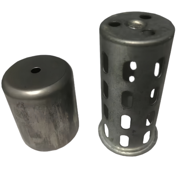
Open area ratio: sizing the perforation pattern to the flow requirement
A perforated filter shell is sized backwards from the flow. The functional requirement is almost never “holes in the metal” – it is a pressure drop at a flow rate, a retention size, or both, tied together by open area ratio. Double the open area at constant flow and the face velocity through the openings halves, and pressure drop falls roughly with the square of velocity. Retention runs the other way: hole diameter sets what the filter stops, and pattern pitch sets how much surface must be devoted to holes without weakening the shell. Three numbers decide whether a filter shell drawing is realistic before any die is cut:
- Hole diameter versus duty: perforated shell work runs from 0.3 mm fine-filtration holes up to several millimeters for coarse straining. The retention requirement fixes the minimum practical hole; the flow requirement then fixes the hole count.
- Open area versus shell strength: at 20 percent open the shell has lost roughly a fifth of its load-bearing section and far more of its stiffness. Above about 30 percent open, a thin shell stops behaving like a structure and starts behaving like fabric; the pattern needs bridges sized for the load, not for appearance.
- Pattern geometry: staggered (hexagonal) pitch packs more holes per area at equal bridge width than a straight square grid – typically 10 to 15 percent more open area for the same structural sacrifice – so a staggered pattern often hits the flow target with thicker bridges and better handling strength.
Piercing after drawing: hole pattern integrity depends on operation order
The single most consequential process decision on a perforated drawn shell is sequencing: the holes go in after the shell is drawn, or they do not go in at all. Piercing before drawing would put thousands of small holes into the flow path of the draw – each hole is a free edge, metal flows around it unevenly, holes ovalize, positions drift, and the thin bridges between holes tear. What starts as a clean pattern becomes a distorted, torn sieve. Every serious perforated shell route draws the cup solid and pierces the pattern into the formed wall.
Piercing a curved wall is not trivial, and the tooling reflects the geometry. A perforating die for a drawn shell carries punches shaped and oriented to the wall’s local tangent, supported by matching die buttons, because a cylindrical punch meeting an inclined wall at an angle shears an oval hole and wears unevenly. The shell locates on its own functional datums – typically the open end and an internal diameter – so the pattern lands where the drawing says relative to the features that matter. Stripper support is the second half of the problem: a thin wall with 20 percent of its material about to be punched has little strength left to resist punch force, and without a hollow-ground stripper holding the wall from inside, the shell dents between hole clusters and the pattern plane waves. Burrs are directed deliberately: the die side of the shear carries the burr, and which side faces the flow is a filter decision, covered below.
Hole diameter relative to wall thickness: the burr and tooling limit
Perforation has a hard geometric limit that drawings occasionally ignore: a punched hole wants to be at least as large as, and preferably comfortably larger than, the sheet thickness. A 0.3 mm punch in 0.5 mm wall grinds at the edge of feasibility – the punch is a fragile needle, the die button is thinner than a hair at its land, tool life collapses and the burnish-versus-fracture balance in the hole wall turns rough. At a hole-to-thickness ratio of 1:1 the process is possible but expensive; at 2:1 and above it is routine; below 1:1, punching stops being the right process at all. When the retention spec demands holes at or below the material thickness, the honest routes are three:
- Thinner wall, if the pressure and handling duty allows – going from 0.5 to 0.3 mm wall can bring a fine pattern from marginal to comfortable, at the cost of shell stiffness.
- Drilling or laser for the fine zone: a small fine-filtration band can be drilled or laser-cut after drawing while the coarse pattern is punched – a cost decision, since drilling per-hole cost dwarfs punching, but honest where physics says no to the punch.
- Etched or woven media bonded into a punched carrier: when retention is far below what perforation can reach at all, the drawn shell becomes the structural carrier and the filtering element a separate medium. We will say so in the review rather than quote a punched pattern that cannot hold tolerance.
Tool wear shows up in the hole wall, and the hole wall is a functional surface on a filter. We track punch condition by sampling hole size and burr height on the agreed plan, and punches are re-ground or replaced on stroke count – a filter shell with furry holes plugs early in service.
Burr direction and flow orientation in a perforated filter shell
Every punched hole has a burr on the die side of the sheet, and on a filter shell the burr’s direction is a functional choice made in tooling. Burr downstream – the flow direction pushing media and particles away from the ragged edge – is the default for shells filtering solids that would hang on burrs and blind the pattern. Burr upstream is occasionally specified when the downstream side must stay smooth for cleaning or a gasket seat, and requires the shell pierced from the opposite side or turned in the tool – the drawing should state the burr side, and a drawing that is silent gets our recommendation before the tool is built.
Burr height is a tolerance like any other. A controlled perforation leaves a burr of 5 to 10 percent of material thickness; a worn tool leaves 20 percent or more, and on a fine pattern that burr is a significant fraction of the hole itself, choking the open area at exactly the holes working hardest. Our acceptance criteria carry an explicit burr-height limit, measured at first article on a sectioned hole and re-checked on the sampling plan. Flow orientation also interacts with structure: a shell seeing pressure differential should be installed with the differential pushing it outward from inside where the geometry allows, because the bridges that survive a lifetime of internal pressure can buckle under modest external pressure – a suction strainer is the classic case, and stiffening rings or a coarser pattern are the levers.
Keeping a highly perforated shell round: stiffness given away to the holes
A drawn cup leaves the press round to within a few hundredths, because the wall is continuous and the draw’s memory holds it. Perforate 20 percent of that wall away and the geometry re-negotiates: every hole is a local stress release, the residual stresses from drawing relax unevenly around the pattern, and the shell distorts – typically into a slight oval with lobes aligned to the pattern’s symmetry, or a gentle banana if the pattern is denser on one side. If it press-fits into a housing or carries a seal ring, that distortion is a functional defect. We control it at three stages. In the pattern design: symmetric layout, so stress release is symmetric – a pattern denser toward one end builds in a bend, and we re-balance the layout or flag the fit consequence. In the piercing tool: full stripper support, so punching force does not add its own denting on top of the stress release. And after piercing, where the fit demands it: a sizing pass – the shell pushed through a round die or over a round mandrel – irons the ovality back out and leaves the shell round to the 0.1 mm class, cheap, fast, and the difference between a shell that drops into its housing and one that needs a press and a prayer.
How we verify hole pattern, open area and burr condition
Release is built around the pattern as a functional system:
- Pattern verification at first article: CMM or optical measurement of hole positions on a defined sample of the pattern – pitch, row alignment, and pattern position relative to the shell’s datums – plus hole diameter and roundness on sampled holes across the pattern’s bands.
- Open area confirmation, calculated from measured pitch and hole diameter on the sampled holes and reported against the specified ratio – not assumed from the die drawing.
- Burr condition: a sectioned hole at first article, burr height measured and burr side confirmed against the drawing’s flow orientation; in production, sampled tactile or visual checks against a boundary sample, with a deburr step if the limit is exceeded.
- Hole wall quality: burnish-to-fracture ratio on the first-article section as the wear baseline for the punch; drift in that ratio on later sections is the early warning before burrs or size go out.
- Shell geometry after piercing: diameter and roundness at the specified stations, length, and concentricity of the ends to the shell axis – after the last operation the shell will ever see, because that is the geometry your housing receives.
- Fit verification where the shell assembles with a press fit or seal: a go-gauge or mating-bore check per the sampling plan.
- Strength sampling for pressure-duty shells: a proof pressure or collapse check on sampled parts per the drawing’s requirement, the result filed with the batch.
- Records: pattern layout, punch stroke count and regrind history, and the measurement plan archived under your part number, so the reorder runs the same pattern to the same limits.
The design decisions behind a part like this — draw ratio, wall thinning, radii and trim — are worked through with numbers in our deep drawn covers guide, and the Precision Deep Drawn Parts pages collect the rest of the family.
Specifications
| Item | Steel Deep Drawn Cups with Perforated Filter Shell |
|---|---|
| Brand | AUNOV |
| Designing | A drawing file or a physical sample starts the review, our engineers reply with a manufacturability assessment and pricing. |
| Tooling | Our own toolroom designs and builds every die, with your part number on the tool record. |
| Samples | First-off samples of the shell are sent with a dimensional report and material certificate. |
| Materials | Carbon steel (SPCC / DC01) leads the stock list for this part, alongside 304 / 316 stainless steel, aluminium, brass and copper, with grade selection confirmed at drawing review. |
| Surface finish | Surface treatment per the drawing: plating, e-coat, powder coating, anodising, passivation, per the drawing. |
| Processing | Deep drawing in stages, in-line annealing where needed, pierced and machined on the same floor. |
| Equipment | Press capacity from 5 to 500 T across mechanical and hydraulic lines, CNC turning centres, climate-controlled CMM room. |
| Tolerance | Drawn tolerances held to +/-0.1 mm, machined features held to +/-0.03 mm. |
| Delivery terms | Prices FOB, with DDP for EU and US on request, T/T or L/C, D/P on repeat business, blanket orders and call-offs supported. |
Frequently Asked Questions
How is a perforated filter shell sized to the flow?
It is sized backwards from the flow: the requirement is a pressure drop at a flow rate and a retention size, tied together by open area ratio. Double the open area and face velocity through the holes halves, so pressure drop falls with the square of velocity.
Why are the holes pierced after the shell is drawn?
Piercing before drawing would put thousands of free edges into the draw flow path; holes ovalize, positions drift and the thin bridges tear. The cup is drawn solid and the pattern is pierced into the formed wall.
How is burr controlled on a perforated filter shell?
Hole diameter relative to wall thickness sets the burr and tooling limit, and the pierce direction is chosen so the burr faces away from the flow it should not impede. Pattern pitch balances retention against shell stiffness.
How is a perforated filter shell verified?
Hole pattern, open area and burr condition are checked, with the shell held round despite the stiffness given to the holes. The typical minimum order is 1,000 pieces with a 24-hour quotation.
Related Products


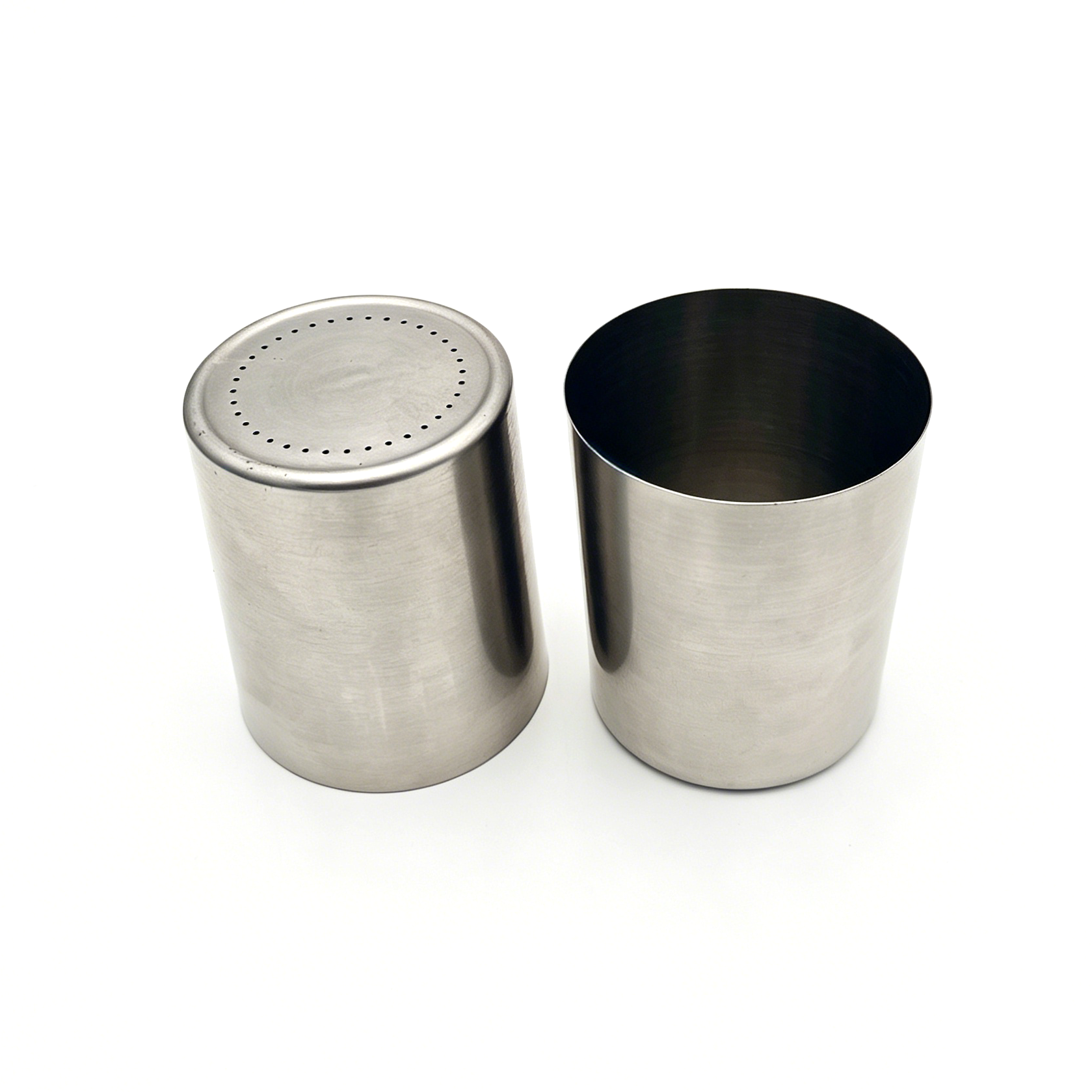
Request a Quote for This Part
Send a drawing or sketch — get material advice, tooling cost and a per-piece price within 24 hours (working days).