
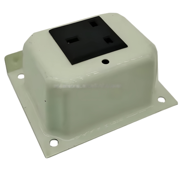
The socket panel changes the box: cutouts, reinforcement and gasket land
A junction box with a socket panel is a different engineering object from a plain enclosure, and the difference is load. A blank steel box only holds its own shape; the moment it carries a panel with sockets, connectors, DIN rail and a wired harness, the box becomes a structure. The panel’s weight and the reaction forces from plugged connectors – a stiff mating connector can push tens of newtons into the panel at plug-in – all route through the box walls and the panel’s fixing points. If the box was drawn thin, say 1.0 to 1.5 mm wall, an unmodified wall deflects visibly under those loads, the gasket seal opens on one side, and the panel’s cutouts go out of position relative to the wall’s gland holes. The countermeasures are forming decisions, essentially free in the die but expensive to retrofit:
- Local stiffening in the draw: shallow beads or stepped ribs around the panel fixing zone and along the deep walls, multiplying a thin wall’s bending stiffness for no added material – a properly placed bead pattern on a 1.2 mm wall outperforms a flat 1.5 mm wall at lower weight.
- A panel land, formed flat. The panel seats on a land or shoulder drawn into the box; its flatness – we hold 0.2 to 0.3 mm as-drawn, machined flat where the panel carries close-tolerance cutouts – decides whether the panel bolts down without racking.
- Cutouts sized for the socket bodies with clearance that accounts for the wall’s own tolerance and the panel material’s thickness; cutout edges are pierced after drawing, on the formed geometry, so their positions stay true to the box features they must align with.
An IP rating is a gasket problem, and a gasket is a flatness problem
Customers specify IP65 or IP67 and treat it as a property of the box; it is a property of a sealing system with four links: the gasket, the gasket land, the closing panel or lid, and the fastener pattern that clamps them. A gasket seals by compressing into the gaps under it: a soft rubber gasket of 1.5 to 2 mm section, compressed 25 to 30 percent, forgives roughly 0.2 to 0.4 mm of land flatness error depending on hardness and whether it is a flat die-cut or a molded profile with a hollow core. Beyond that error the low spots sit under-compressed and the box leaks at the first rain or washdown.
Drawn boxes fight flatness in two places. The land ring around the opening is a drawn feature – it comes out with residual dish and takes the trim’s edge distortion at its boundary – so it is either restrike-flattened to the 0.1 to 0.15 mm class or machined flat to better than 0.1 mm for molded or hollow-core gaskets. The pressure side deserves equal respect: IP67 implies immersion and a pressure differential, the walls see it, a large flat wall on a thin box bows outward, and if it bows enough the gasket unloads at mid-span. That is why large IP67 boxes get stiffening ribs and closer fastener spacing than the same box at IP54 – and why we ask for the gasket specification when we quote: the land, boss heights and wall stiffness are designed around the gasket’s compression curve, not vice versa.
Cable gland positions: piercing the wall after drawing, never before
Gland holes look like the simplest feature on a junction box and are the most common place the process goes wrong. The naive route – pierce the holes in the flat blank, then draw the box – is cheap and wrong. Drawing moves metal: a hole on a wall that will be drawn sees its position and shape dragged by the draw, more the deeper the wall, and a round hole near a curved or corner-adjacent wall comes out oval. The box ends up with gland holes individually the right size and collectively in the wrong places. Our route is fixed: draw first, pierce second, on the formed box, in a piercing die that locates from the box’s own functional datums – the panel land and the open rim – so the pattern is true to the features the assembly cares about. The specifics:
- Hole size is a standard question. Gland bores map to standard gland threads – M16, M20, M25 are the common families – and we punch to the thread’s tapping size or a clearance size for the gland’s locknut, per the drawing callout.
- Minimum edge distance matters on a drawn wall. A hole too close to a corner radius or flange bend distorts during piercing – the wall cannot back up the punch – and the hole tears or dishes. We hold gland holes at least 2.5 to 3 times hole diameter from bends, or add a local flat to the corner in the die.
- Deburr both faces. The inner burr can cut cable insulation; the outer burr breaks the sealing washer’s contact. Gland holes are deburred inside and out, and the burr check is part of the release sheet.
Box depth versus panel deflection under hardware weight
Depth is the dimension customers adjust last and should adjust first. A shallow box crowds the harness and sockets; a deep box gives wiring room but multiplies the deflection problem, because every wall gets bigger relative to its span and the socket panel – now cantilevered deeper – transfers hardware weight and connector loads into longer, more compliant walls. Finding the depth where the box holds the gasket compressed on all four sides with the panel fully loaded is a deflection calculation, not a preference. The arithmetic is simple at review stage: a flat steel wall of span L and thickness t deflects under a central load in proportion to L to the fourth over t cubed – a 20 percent depth increase in every dimension, at constant wall thickness, roughly doubles wall compliance. All the structural fixes – a rear panel support, a mid-wall rib, fixing points moved closer to the load – are free in the draw die and expensive as sheet-metal retrofits.
The acceptance side of deflection is functional: with the fully loaded panel installed and the lid torqued, the gasket stays compressed everywhere. We verify by a witness-line test at first article – gasket installed, a thin film on the land, lid closed and opened, the transfer pattern inspected for continuous contact – and by gap gauges around the closed lid at specified points.
EMC shielding continuity with a removable socket panel
A steel junction box is a natural Faraday cage, and many installations buy the steel version specifically for EMC – then lose the shielding at the seams. Shielding effectiveness is dominated not by wall material but by joints: a gasketed lid joint without a conductive path is a slot antenna, and a socket panel full of cutouts is a screen door. Continuity is engineered feature by feature:
- Conductive gaskets – wire-mesh elastomer, oriented-wire-in-silicone, or finger stock – replace or supplement the environmental gasket at lid and panel joints. They need bare-metal contact lands, which means masking or post-machining the coating at the gasket path.
- Bare contact spots at screw points: each fastener is a ground point if the coating under it is controlled; we mask the screw seats or specify conductive coating there. Screw spacing on a shielded joint is set against the frequency of interest: seam gaps behave as slot antennas, and the rule of thumb keeps gaps well under a twentieth of the highest wavelength that matters.
- Panel cutouts are the escape path: sockets and connectors should be conductive-bodied and bonded to the panel, or carried in shielded housings; a plastic panel needs a conductive coating or a metal backing plate to close the aperture.
- Every cable entry is an antenna: gland holes need EMC glands or filtered feedthroughs where the shielded rating must survive the wiring, and we punch the gland bores to suit the EMC gland family the drawing specifies.
How we verify sealing and panel fit on junction box enclosures
Each part number is released and re-verified on a written plan:
- Land flatness on the gasket path by CMM or surface plate at first article and by gauge in production, to the class the gasket specification requires – as-drawn flattening for soft flat gaskets, machined land for molded or hollow-core sections.
- Gland hole pattern by go-pin fixture every batch, plus CMM verification of hole size, roundness and position to drawing datums at first article; burr check on both faces of every hole.
- Panel land and fixing boss geometry – land flatness, boss heights and positions – gauged to the die record, because panel fit and lid clamp both hang off them.
- Seal witness test at first article: gasket and full panel load installed, lid torqued to specification, contact pattern inspected for continuity around the full perimeter; gap gauges at specified points around the closed lid.
- Deflection check under load where the panel carries heavy hardware: measured wall and lid deflection at specified points with the rated load installed, against the agreed limit.
- Coating and masking verification: film build on walls and interior, masking integrity on gasket lands and any conductive contact seats, per the painting plan for the part number.
- Continuity checks for shielded variants: point-to-point resistance across lid and panel joints at specified pairs, with the acceptance value agreed from the shielding requirement.
- Records: first-article dimensional report, witness-test photographs, batch sampling data, and the die settings archive under your part number – so a reorder reproduces the box exactly, gasket performance included.
If you are weighing drawing against machining or welding for this geometry, the guide to deep drawn covers sets out where each route wins; the full Precision Deep Drawn Parts range is linked from the overview page.
Specifications
| Item | Deep Drawn Steel Junction Box Enclosure with Socket Panel |
|---|---|
| Brand | AUNOV |
| Designing | Send us your 2D drawing, or mail a sample for measurement, you get a DFM review together with the quotation. |
| Tooling | Every die designed and built in our toolroom, with your part number on the tool record. |
| Samples | Sample parts arrive with dimensional data and material certification. |
| Materials | Carbon steel (SPCC / DC01) is the primary stock for this part, alongside 304 / 316 stainless steel, aluminium, brass and copper, with grade selection confirmed at drawing review. |
| Surface finish | Surface treatment per the drawing: plating, e-coat, powder coating, anodising, passivation, per your print. |
| Processing | Staged deep drawing with in-line annealing where needed, then pierced and CNC-machined in house. |
| Equipment | 5-250 T mechanical presses plus 250-500 T hydraulic presses, CNC turning and milling cells, a climate-controlled CMM room. |
| Tolerance | Drawn tolerances held to +/-0.1 mm, with machined features to +/-0.03 mm. |
| Delivery terms | FOB as standard, DDP available for EU and US destinations, T/T or L/C, D/P on repeat business, call-off schedules and blanket orders supported. |
Frequently Asked Questions
Why is a junction box with a socket panel a different object from a plain box?
A blank steel box only holds its own shape; once it carries a panel with sockets, connectors, DIN rail and a harness it becomes a structure. The panel weight and connector plug-in forces route through the walls and fixing points, so a thin drawn wall deflects, the gasket opens and the cutouts drift out of position.
What does an IP65 or IP67 rating depend on in a drawn box?
It is a property of a sealing system with four links: the gasket, the gasket land, the closing panel or lid, and the fastener pattern. A soft gasket of modest section compressed a controlled amount forgives a small land flatness error; beyond that the box leaks at the first rain or washdown.
Why are cable glands pierced after drawing, never before?
Piercing before drawing puts free edges into the draw path where the wall distorts and holes drift; glands are pierced into the formed wall after drawing so position and roundness are held. The panel cutouts are formed and then machined to the same logic.
How is a junction box enclosure verified?
Sealing and panel fit are checked on the first article, with EMC continuity across the removable panel verified where the duty requires it. The typical minimum order is 1,000 pieces with a 24-hour quotation.
Related Products


Request a Quote for This Part
Send a drawing or sketch — get material advice, tooling cost and a per-piece price within 24 hours (working days).