
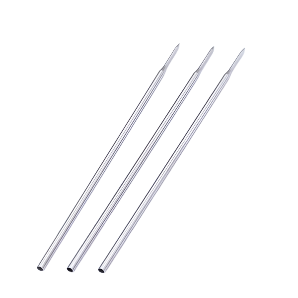
A 300 mm needle with a 0.4 mm bore is a straightness problem first
A long thin capillary needle tube – think 200-500 mm long, outside diameter under 2 mm, bore under half a millimetre – is a part whose dimensions are almost all easy except the one nobody can see. The diameters are held by drawing. The wall is held by the schedule. What is hard is straightness, because a needle that is bowed cannot find its target, and a 0.3 mm bow over 300 mm is invisible in the hand and fatal at the point of use.
Straightness on a slender drawn tube is lost in three places, and the drawing plan has to anticipate all three:
- During drawing, the tube wraps residual stress around itself unevenly, and the last pass leaves a slight coil memory. A tube drawn in coil form arrives at cutoff with curvature; a tube drawn in straight bars arrives straighter but costs more per metre.
- At cutoff, parting loads bend the slender section and the cut end’s heat or burr can locally upset the tube. Below 2 mm OD the cutoff method is a process choice – abrasive cut, shear, or rotary knife – and the choice shows up directly in the end straightness of the first 5 mm.
- In handling, a 0.4 mm wall-less tube bends under its own weight when picked up by one end. Everything after straightening – cleaning, annealing, inspection, packing – must support the full length or it reintroduces the bow the straightener just removed.
We straighten on rotary or roll straighteners that put the tube through alternating flex cycles, and we verify straightness the way it will be used: the needle is rolled on a precision V-rail or floated on an air table and the total indicated runout read along the length, against a drawing callout that should be stated as a bow per length – 0.2 mm over 300 mm is a robust production figure for this slenderness; below 0.1 mm over 300 mm the part needs individual straightening and 100 percent inspection, and the quotation will say so.
Reduction passes and the smallest bore we will commit to
Capillary needles are made by staged reduction from larger stock, and the arithmetic of the stages sets the floor of what is manufacturable. A 0.4 mm bore with a 0.15 mm wall begins life as perhaps 6 x 1 mm stainless steel stock, and reaches its final size through eight to twelve drawing passes with intermediate anneals – each pass a die and a plug, or a die and a floating mandrel, taking 20-30 percent area reduction and a correspondingly smaller step in diameter.
What the pass schedule really controls is bore uniformity along the length. A single aggressive pass leaves the bore slightly stepped at every die change; a schedule of small passes keeps the bore smooth but multiplies the operations. The wall-to-bore relationship shifts along the way too: passes with fixed-plug drawing thin the wall proportionally, while sinking passes (die only, no plug) thin the wall less predictably and can leave the bore slightly rough. We use sinking passes only where the bore is not functional, and fixed-plug or floating-plug passes wherever the bore has a stated tolerance.
The practical floors, which we state in every quotation for this family:
- Bore tolerance at 0.3-0.5 mm bore: +/-0.02 to +/-0.03 mm by plug drawing, verified by precision pin gauges at both ends and air-flow correlation on samples.
- Below 0.3 mm bore, the bore is specified by flow rate rather than by diameter, because gauge measurement inside a 0.2 mm hole 300 mm long is a research exercise, not an inspection operation. A stated flow class – the flow of a defined fluid at a defined pressure differential – is measurable, repeatable, and honest, and we will propose it in the review when the drawing asks for a diameter we cannot verify.
- Wall below 0.1 mm is drawable but fragile; we quote it with the handling plan attached – shipping on support troughs, not in bags – because a wall that thin does not survive a parts tumbler.
- Concentricity of bore to OD on a finished needle is held to better than 0.03 mm TIR by rotating the stock between passes and finishing with plug passes; eccentricity on a capillary is a wall problem, and the wall is the smallest feature on the part.
Burr-free cutoff: the end of a needle is most of its function
On a needle tube, the end geometry is not a finishing detail – it is the working feature. A dispensing needle’s flow characteristics are set by the orifice edge; a probe needle’s insertion force is set by the tip condition; a hypodermic-adjacent part’s whole function lives in the last millimetre. And the cutoff operation, on a thin wall, leaves either a burr, a rolled edge, or a heat-affected lip unless the method is chosen for the wall.
The failure modes by cutoff method:
- Shear cutoff is fast and burr-prone on thin walls: the tube walls fold inward before the punch completes the cut, leaving an internal burr that reduces the effective bore at the tip by 10-30 percent. On a flow-critical needle that is a functional change hiding inside a dimensionally perfect part.
- Abrasive cutoff leaves no burr worth the name but embeds abrasive in the cut face and heats the edge, and on stainless steel it can locally tint the end. Fine for a needle that gets a later finishing pass; not acceptable as a final operation.
- Rotary knife cutoff – the tube is scored and snapped, or cut by a rotating blade with the tube supported a millimetre from the cut – is the cleanest mechanical option on thin walls and our default for needles below 2 mm OD. Edge rollover is minimal and the bore stays open.
- EDM or laser for tips that need a shape – bevels, bent tips, side ports – with the recast layer and heat tint removed by a finishing pass. Expensive per cut, and reserved for tips the drawing actually shapes.
Luer fit or plain end: what the mating half decides
A needle only works as part of a connection, and the mating half at the rear end decides more about the needle’s specification than the needle’s own body does. The common rear-end standards and what each demands from us:
- Plain ends – cut, deburred, square or chamfered. The simplest specification, and the right one when the customer does the joining: needles supplied to a sub-assembly house that brazes or bonds the needle into its fitting downstream want plain ends, clean and dry, with no finish that interferes with brazing.
- Slip luer (6 percent taper) – the taper is a turning operation on the needle end: a conical surface whose taper angle and gauge-line diameter have to be verified by luer gauge or CMM. On thin-wall needle stock, turning the luer means thick-walled stock at that end, so a luer needle is often drawn in two wall zones – thick at the fitting end, thin at the working end – and the wall transition is a drawing-schedule feature, not a machining one.
- Threaded or press-fit ends – threads cut on the needle tube where the wall allows, or the needle press-fitted into a turned fitting. Threads on 0.15 mm wall are not a real option; the press-fit route with a crimp or brazed joint is, and the joint’s strength then becomes part of the part’s specification, verified by pull test on samples.
- Bent, flared or swaged rear forms – where the rear end seats in a moulded or overmoulded housing, the rear geometry is whatever the housing needs: a flange for the plastic to grip, a bend for orientation, a barb for a hose. These are formed features with their own tolerances, and they interlock with the straightness callout because every forming step at the rear puts stress into the length.
Bore cleanliness on a part you cannot swab
A capillary needle’s bore is the least accessible surface we produce: 300 mm long, 0.4 mm across, and it carried drawing lubricant, soap film and die debris through every pass of the schedule. The bore arrives at cleaning needing it, and it cannot be wiped, brushed or visually inspected. Cleanliness on a needle is therefore a process specification verified by proxy, and the proxies need to be agreed, not assumed.
Our needle cleaning chain, in order:
- Immediate post-draw flush – the schedule alternates drawing passes with in-line solvent flushes, because lubricant left in a 0.4 mm bore through an anneal cycle carbonises into a varnish that no later bath fully dissolves. Cleaning early is cheaper than cleaning hard.
- Ultrasonic alkaline immersion in racks that hold needles vertical and uncrowded, so the cavitation reaches every bore and the released soil drains out rather than re-depositing.
- Hot DI water purge – flowed through each bore, with the effluent checked; this step removes both the alkaline residue and the remaining particulate.
- Citric or nitric passivation of the stainless steel surfaces, bore included, in the same vertical-rack immersion.
- Filtered nitrogen blow-dry with each needle held tip-down, then individual protective packaging for cleanliness-critical orders.
How we verify a long needle when a pin gauge cannot reach the middle
Needle verification accepts the physical fact that the bore’s middle cannot be touched, and builds the report around what can be measured directly, what is controlled by process, and what is verified by function:
- OD by laser or low-force micrometer at three or more stations along the length, every part for flow-critical orders, lot sample otherwise.
- Bore by precision pin gauge at both ends, into a stated engagement depth – pin gauging a 300 mm bore end-to-end is not a floor operation, and the drawing’s bore callout should be written as it will be gauged.
- Bore along the length by air-flow correlation: each needle’s flow of dry filtered air at a stated differential pressure is measured against the flow class, and the flow number is the bore’s mid-length witness – an occlusion, a partial collapse or a lubricant blockage all read as low flow, which is exactly the point.
- Wall by section on lot samples at both ends, plus ultrasonic wall where the wall is a stated minimum for pressure duty.
- Straightness by V-rail rotation or air-table float, total bow reported per the drawing’s bow-per-length callout, gauge method stated.
- Tip and end condition under 30x magnification on lot samples: burr, edge rollover, chamfer or radius present as specified, and for flow needles the effective tip orifice checked by flow.
- Rear-end form per the drawing: luer ends gauged 100 percent with hardened luer gauges, plain ends verified by the burr-free check, formed ends verified by their own fixtures.
- Cleanliness by gravimetric flush on samples for needles ordered to a cleanliness class; flow-test residue proxy for flow-class needles.
- Material certificate and drawing condition – temper, anneal state, passivation record – with the shipment, so the needle’s straightness, cleanliness and temper are documented facts rather than assumptions.
Send the drawing or a sample needle, including its mating half if it has one. The review that comes back with the quotation will state the pass schedule’s endpoints, the bore tolerance or flow class we commit to, the straightness callout as bow-per-length, the end treatments per end, and the verification method for each – which is the whole argument of this page, in one list.
This part belongs to our Deep Drawn Tubes & Sleeves range. The deep drawn tubes & sleeves pages collect the process notes, common materials and inspection points behind every product in the family.
Specifications
| Item | Stainless Steel Long Thin Capillary Needle Tubes |
|---|---|
| Brand | AUNOV |
| Designing | Share your print, or send a part to be measured, our engineers reply with a manufacturability assessment and pricing. |
| Tooling | Dies designed and built in our own toolroom, stored under your part number. |
| Samples | First-off samples are sent with dimensional data plus material certs. |
| Materials | 304 / 316 stainless steel leads the stock list for this part, alongside carbon steel (SPCC / DC01), aluminium, brass and copper, per the drawing. |
| Surface finish | Plating, e-coat, powder coating, anodising or passivation as the drawing calls out, selected against the drawing requirement. |
| Processing | Staged deep drawing, with in-line annealing where the draw ratio requires, then pierced and machined in house. |
| Equipment | 5-250 T mechanical presses plus 250-500 T hydraulic presses, in-house CNC cells and a temperature-controlled inspection room. |
| Tolerance | Drawn tolerances held to +/-0.1 mm, +/-0.03 mm after machining. |
| Delivery terms | Standard terms FOB, DDP offered to EU and US, T/T or L/C, with D/P for repeat business, blanket orders and call-offs supported. |
Related Products


Request a Quote for This Part
Send a drawing or sketch — get material advice, tooling cost and a per-piece price within 24 hours (working days).