
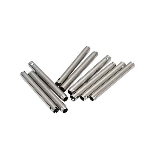
A stepped pin is a datum chain with three diameters in it
A stepped tube pin – a hollow cylindrical part with two or more coaxial diameters along its length – looks like a simple lathe job and is actually a metrology problem. The diameters are easy. The requirement that matters is the relationship between them: the small end’s axis relative to the large end’s axis, and both relative to the bore. A pin that locates one part in another does its job by concentricity, and a stepped pin with a 0.05 mm runout between its sections is a pin that jams in its hole halfway through the press-fit, or wears its bore oval within a season.
The datum chain has to be chosen before the process, and there are only three sensible options:
- Bore as datum. The pin is mounted on a tapered or expanding arbor, and both OD sections are turned in reference to the bore. This is right when the pin fits over a shaft or post – the bore is what locates it in service, so the bore should locate it in machining.
- Large OD as datum. V-work or collet on the large end, everything else referenced to it. Right when the large end presses into a housing, because the housing fit is the service datum.
- End-face as datum. Face-and-drive work between centres or against a face plate, with both diameters turned in one setup. This is the strongest chain when the pin seats on its shoulder, because one setup means the step relationship is set by the machine, not by a re-chuck.
The hollow section adds a wrinkle solid pins do not have: the bore itself can be eccentric to the OD, and on a thin-wall stepped pin a 0.02 mm bore eccentricity converts directly into 0.02 mm of wall variation around the circumference. For pins where the wall matters – magnetic cores, pressure-balanced parts, anything that must not imbalance a rotating assembly – we verify wall at four points on both sections, not just the diameters.
Two steps or three: how the count changes the process plan
Step count is the biggest single driver of process and price on these parts, more than material, more than tolerance – because each step is an additional setup in which the datum chain must be re-established, and every re-establishment adds runout risk and cost.
A two-step pin – large OD, small OD, one shoulder – is a one-setup part in a sliding-headstock CNC lathe: bar fed, all diameters turned in sequence, parted off, done. The concentricity between the steps is set by the machine’s spindle accuracy, and we hold 0.01-0.02 mm without heroic effort. Total runout between the steps is a function of the collet, the bar condition and the cuts, all of which are process decisions we make once and hold.
A three-step pin starts a conversation. The middle step is accessible, but a deep step stack – especially on a long thin part – reaches the limit where the middle diameter is turning 15-20 diameters out from the guide bushing, where deflection and thermal growth start competing with the tolerance. At that point the honest options are:
- Turn in two setups with a verified datum transfer. The second setup re-establishes the datum on the same feature the first setup created, and the transfer accuracy is measured and recorded. This holds around 0.02-0.03 mm cross-setup runout and is the workhorse answer.
- Draw the steps, don’t turn them. A tube pin from drawn tube stock gets its OD steps by swaging or drawing reductions, which produces a grained, stronger, cheaper step at a looser tolerance (+/-0.05 to +/-0.1 mm), then machine only the functional ends. For a pin with two decorative steps and two functional ones, that hybrid is often half the machining cost.
- Split the tolerance honestly. If the drawing gives every step +/-0.02 mm and runout 0.01, but only the two end steps locate anything, widening the middle step to +/-0.1 mm is free performance. The review proposes this often, and the drawing usually agrees with itself once the question is asked.
Swaging, turning or drawing the transition: choosing per step
Every step on a tube pin has a transition zone, and there are three ways to make it, each with a different shape, cost and tolerance signature. Getting the method right per step – rather than one method for the whole part – is where a good process plan earns its keep.
- Turned transitions are exact: the shoulder is square within a degree, the corner can carry a chamfer or radius per the drawing, and the diameters hold +/-0.02 mm or better. The cost is machine time, and the limit is reachability. The transition is also sharp – a turned step is a stress raiser in bending, which matters on a pin that carries load.
- Swaged transitions are formed: the tube is driven through a die that reduces its OD and the step is a 30-45 degree conical blend with radiused tangents. Tolerance is +/-0.05 to +/-0.1 mm, the surface is work-hardened and smooth, and the step is inherently fatigue-friendly because there is no sharp corner. Swaging is the cheapest step per millimetre of any method, and on stainless steel it adds strength to the small end by cold work.
- Drawn transitions sit between the two: a redraw of the tube with a stepped die produces a longer, straighter small section than swaging, with wall control from the plug. This is the method for long small ends – a 30 mm reduced section on a 100 mm pin – where turning would be deflection-prone and swaging cannot reach the length.
Where the drawing wants a swaged shape at turned tolerances, the answer is a hybrid: form the step by swaging for strength and stock-to-shape, then finish-turn the small diameter in the same machine cycle. The swaged step carries the load, the turned diameter carries the fit, and the pin costs less than either pure method at the same drawing.
Concentricity between steps is a rotation problem, not a size problem
The most common tolerance error on stepped pin drawings is treating concentricity as though perfect sizes made it free. They do not. Two diameters can each be dead on nominal and still be 0.04 mm apart in axis, because the axes are set by the setup, not by the size cuts. And the inverse holds: a pin with every diameter at the edge of its size tolerance can be perfectly concentric. Concentricity is bought by setup strategy and verified by rotation, and the drawing that specifies it without saying how it will be checked is inviting a disagreement at receiving inspection.
The verification methods, in the order a shop will reach for them:
- Runout between centres. The classic: pin supported between centres or in a V-block on the reference OD, rotated, indicator read on each step. This is what most drawings implicitly assume, and it is fast and honest for a ground or turned finish.
- V-block runout. No centres needed, but the V-block reads the reference OD’s own roundness into the result – a 0.01 mm out-of-round reference shows up as 0.005 of apparent runout. On a drawn or swaged reference step, this matters, and the inspection instruction must state it.
- CMM axis comparison. Each section probed as a set of circles, axes computed, runout derived. Slower, but it separates roundness, size and true position properly, and it is the referee method when a V-block reading and an assembly symptom disagree.
Chamfers, radii and what a tube needs before it is a pin
Pin drawings concentrate attention on the diameters and treat the ends as an afterthought, and the ends are where pins fail in service. A pin is inserted into something, and insertion is a race between the lead-in geometry and the assembly operator’s patience. A pin with a square-cut end and a burr is a pin that shaves aluminum oxide, brass or stainless steel debris into the bore it enters, and the debris is the beginning of a wear story.
The end features that matter, and the numbers we hold them to:
- Lead-in chamfer on the insert end: 15-30 degrees is the functional range. Below 15 degrees the chamfer is too long and adds cost without guiding better; above 30 degrees it stops guiding before the pilot diameter engages. We standardise on a 20-degree lead with a 0.3-0.5 mm chamfer depth unless the drawing says otherwise.
- Burr condition after cutoff: a parted or cut tube pin carries either a burr or a rolled edge at the cut, and on a hollow pin the bore’s inner edge is where the burr hides. Our cutoff is followed by a deburring pass that puts a 0.1-0.2 mm inner chamfer or radius on both bore edges, and “burr-free” on our drawings means verified by feeler, magnifier and a cotton-swab pass on the bore edges of lot samples.
- Shoulder face condition: the shoulder that seats against the mating part should be turned clean in the same setup as the adjacent OD – a shoulder faced in a second setup carries the setup’s runout into the seat, and a pin seated on a face 0.02 out of square is a pin installed crooked by a quarter of a degree, which at 50 mm of length is 0.2 mm of tip runout.
- Wall-edge radii on the tube ends: for pins handling fluid or gas, the bore edge radius is a flow feature, not a finish nicety – a sharp bore edge at the flow entry separates the flow early and adds losses a 0.2 mm radius avoids.
How we verify a stepped pin in one setup across three diameters
Verification is built around the datum chain the review fixed, and the sequence is the same for every lot so a repeat order is measured the way the first article was:
- Diameter verification per step – micrometer or air gauge as the size suits, three stations along each step where the step is long, at edge and mid-length where it is short, against the drawing’s size tolerances.
- Runout between steps by rotation, method stated on the report: between centres for turned pins, V-block with the reference OD’s roundness noted for drawn or hybrid pins. The acceptance number is the drawing’s; the fixture is the part number’s.
- Bore verification – plug gauge or air gauge at each bore step, with bore-to-OD concentricity measured on the CMM on lot samples where the drawing calls it.
- Lengths and shoulder positions in one setup on the height gauge or CMM, so step spacing is measured as a chain from the reference face, not as independent lengths that each absorb their own error.
- End condition: chamfer angle and depth on the insert end, shoulder face squareness, and the burr-free check by feeler, magnifier and swab on the bore edges.
- Wall check on thin-wall pins: four-point wall measurement on each section for pins with a wall or balance requirement, reported per section.
- Material and condition: PMI on lot samples for stainless steel, hardness on lot samples where the drawing states a temper or the service is cyclic – a swaged stainless steel step is measurably harder than the parent, and the report should show it.
- First article carries the full report and material certificate; production lots carry the same measurements at the stated sampling, with the same fixtures and the same stated methods.
Send drawings or a sample pin to be reverse-measured. The review that returns with the quotation will state the datum chain, the per-step method – turned, swaged, drawn or hybrid – the tolerances each method holds, and the verification method for every callout, so the part that ships assembles the way the drawing intended.
Deep Drawn Tubes & Sleeves is the parent range for parts like this one; the overview page gathers the tooling logic, finishing options and tolerance notes that apply across the family.
Specifications
| Item | Stainless Steel Precision Stepped Tube Pins |
|---|---|
| Brand | AUNOV |
| Designing | Share your print, or send a part to be measured, DFM feedback is returned with the quote. |
| Tooling | Tooling designed and cut in house, held under your part number. |
| Samples | Samples for approval come with a dimensional report and material certificate. |
| Materials | 304 / 316 stainless steel is the primary stock for this part, alongside carbon steel (SPCC / DC01), aluminium, brass and copper, and the grade is fixed at the drawing review. |
| Surface finish | Plating, e-coat, powder coating, anodising or passivation, per your print. |
| Processing | Multi-stage drawing, annealed in line where wall thinning calls for it, then pierced and CNC-machined in house. |
| Equipment | Mechanical presses 5-250 T and hydraulic presses 250-500 T, in-house CNC cells and a temperature-controlled inspection room. |
| Tolerance | Tolerances to +/-0.1 mm as drawn, +/-0.03 mm after machining. |
| Delivery terms | FOB is standard; DDP offered for EU and US, T/T or L/C, with D/P for repeat business, call-off scheduling supported. |
Related Products


Request a Quote for This Part
Send a drawing or sketch — get material advice, tooling cost and a per-piece price within 24 hours (working days).