
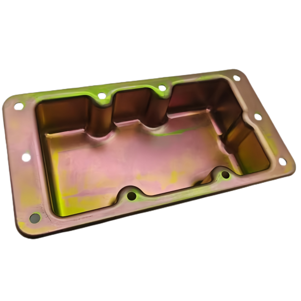
The Steel Deep Drawn Rectangular Tray with Mounting Flanges is drawn carbon steel (SPCC / DC01) with two functions stacked in one part: a formed cavity that carries whatever it carries, and a pair of flat mounting flanges along the long edges that bolt the tray to structure. The rectangular geometry makes the corners behave like a box draw while the straight long walls behave like simple bending, and the flanges have to survive both the forming and the trimming with their hole pattern and flatness intact. We form these trays on presses across the shop’s tonnage range, and this page covers the engineering that decides whether the tray mounts when it arrives.
Mounting holes on tray flanges: pierce before or after forming
The bolt holes in the mounting flanges are the feature that decides the whole process sequence. Pierced in the flat blank, they ride on material that the draw then pulls and stretches: holes near the cavity edge displace inward and elongate toward the tray walls, and a hole that was 6.1 mm round and positioned 12 mm from the bend can finish 6.4 × 5.9 mm and a millimeter off position — enough to turn a bolt-through assembly into a rework station. The distortion shrinks with distance from the cavity, but the flange width is fixed by the design, so the geometry decides how much of the pattern sits in the stretched zone and we do not get to choose.
Our default on this family is post-form piercing: the tray draws and trims first, then the flange holes pierce in a second station located off the trimmed cavity profile, and the pattern lands within +/-0.15 mm of the formed geometry — the geometry the mating bolts actually care about. The cost is a second die station; the alternative is pre-piercing in the blank with expanded, flow-compensated hole positions and diameters tuned per hole from tryout data. We quote both when the volumes justify the engineering, and where the tray’s holes carry tight true-position callouts, post-form piercing is the only route we will stand behind. What we refuse is the silent version: pre-piercing at nominal and letting the field discover the drift.
Corner development on a rectangular draw and the blank it needs
A rectangular tray is a box draw, and the corners dominate its blank development exactly as on square work. The corner material converges as it flows, compresses, and thickens — a rectangular tray corner run without relief shows corner thickening of 5 to 10 percent on SPCC, and without a blank shape that removes the surplus, that thickening expresses itself as flange wrinkles that lock into the wall. The blank we develop is a rectangle with arced corners whose radii scale with corner depth, plus trim stock distributed unevenly: more at the corners, where the flow is violent, less along the straight stretches where the material simply bends over the die radius.
The long straight walls are the forgiving part, and their forgiveness is worth spending deliberately. Along a straight wall, material feeds inward with almost no stretching, so a deep straight side costs far less formability than a deep corner — which is why the same tray form factor can gain straight-side depth cheaply but corners only expensively. When a drawing tightens the corner radius or deepens the cavity at the corners without touching the straight walls, the part crosses from one-stroke forming into staged drawing, and we quote the second die rather than absorb the scrap. The ratio of corner depth to corner radius is the number we check first on every new tray drawing in this family for exactly that reason.
Keeping the tray bottom flat when the draw wants to bulge it
Tray bottoms bulge for one prosaic reason: trapped air. A wide flat bottom forming against a solid punch seals against the die surface, and the air pocket under the forming floor compresses, heats, and finally lifts or domes the panel — the classic pillow-bottom tray. The cure is venting: vent pins and channels drilled into the die so the cavity breathes from the first millimeter of stroke. We design the vent pattern per tray footprint on every tool in this family, because a tray that domes 1 mm in the middle fails a flatness callout that nothing in the forming parameters can recover.
The second bottom threat is the draw itself stretching the floor. On a tray drawn deep for its corner radius, the bottom center can thin and crown as material pulls outward to feed the walls; the defense is a punch-side stock condition and sufficient blank size that the flange feeds the walls rather than the floor donating material to them. We verify bottom condition on first article by thickness mapping across the floor — center, quarter points, corners — and the map repeats on sampled production parts. A tray bottom that thins evenly and predictably is a healthy process; one that thins locally is telling us the lubrication or the blank holder has drifted, and we read it that way rather than waiting for the flatness gauge to fail the lot.
Flange flatness after trimming: what residual stress does next
When the trim die cuts the tray to final outline, it releases forming stresses that the untrimmed flange was carrying — and the flange moves. On long trays the effect is measurable: an edge that lay flat as-drawn can bow 1 mm or more over its length within hours of trimming, because the trimmed-away stock was holding the flange in tension. We schedule accordingly. Trimming runs before any flatness-critical inspection, and where the spec is tight, a flange-coining or stress-relieving station follows the trim so the flange settles into its final state under control rather than in the shipping crate.
Ageing is the longer tail of the same physics. Carbon steel trays formed hard hold residual stress that relaxes over weeks; a tray measured flat at final inspection can arrive less flat a month later. Our defense is process-side: form with the blank holder window that keeps corner compression moderate, trim with the outline balanced around the part’s neutral axis, and coin where the drawing demands precision. Where a customer’s application cannot tolerate drift at all — clamping faces, sealing lands — we say so at quotation and the coining operation goes in the routing from day one, priced and scheduled, not discovered after the first field complaint.
How we verify rectangular trays with mounting flanges
Release checks on this family follow the geometry’s own order of failure:
- Flange hole true position to the trimmed cavity datum on a CMM or with a position gauge covering the full pattern — corner holes and cavity-edge holes first, since those sit where forming distortion concentrates.
- Flange flatness with the tray supported at its mounting points, measured after the trim and any coining have run, at a settle interval the process sheet defines — never immediately after the cut, when the flange has not yet told the truth.
- Corner wall thickness against the first-article reference at the punch radius zones, both ends of the tray, sampled per lot.
- Bottom flatness and thickness map on sampled parts — center and quarter points — catching both trapped-air doming and floor thinning signatures.
- Hole edge condition on the pierced flange holes: burr side, burr height on sampled holes, since a flange bolted down on a ragged burr sits on a washer’s worth of distortion.
- Trim edge condition and overall outline against the drawing, with the trim die’s wear tracked by edge quality on a parts-per-touchup count.
- Material certification per heat, filed with the forming and trim process record for the lot.
Every check on the list exists because a tray with this geometry failed that way somewhere, once — the list is the memory, and the lots that pass it are verified against the part’s real history rather than a generic checklist.
This part belongs to our Custom Metal Stamping Parts range. The custom metal stamping parts pages collect the process notes, common materials and inspection points behind every product in the family.
Specifications
| Item | Steel Deep Drawn Rectangular Tray with Mounting Flanges |
|---|---|
| Brand | AUNOV |
| Designing | Send us your 2D drawing, or mail a sample for measurement, the quotation comes back with a manufacturability review attached. |
| Tooling | Every die designed and built in our toolroom, each die held against your part number. |
| Samples | Sample parts arrive with a full dimensional report and mill certificate. |
| Materials | Carbon steel (SPCC / DC01) is the primary stock for this part, alongside 304 / 316 stainless steel, aluminium, brass and copper, and the grade is fixed at the drawing review. |
| Surface finish | Finish options: plating, e-coat, powder coating, anodising or passivation, selected against the drawing requirement. |
| Processing | Deep drawing in stages, in-line annealing where needed, then pierced and machined in house. |
| Equipment | Press capacity from 5 to 500 T across mechanical and hydraulic lines, CNC turning and milling cells, a climate-controlled CMM room. |
| Tolerance | +/-0.1 mm on as-drawn features, +/-0.03 mm on machined features. |
| Delivery terms | FOB standard, DDP offered for EU and US, payment T/T or L/C, D/P for repeat accounts, call-off scheduling supported. |
Related Products


Request a Quote for This Part
Send a drawing or sketch — get material advice, tooling cost and a per-piece price within 24 hours (working days).