
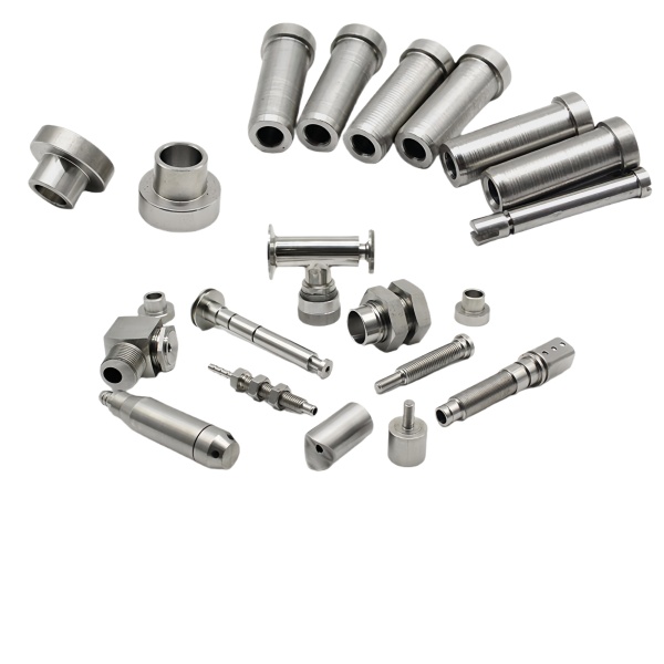
The Stainless Steel CNC Machined Stepped Pins and Fittings are turned from austenitic grades — 304 and 316 for the bulk of the family — and stepped pins concentrate every difficulty austenitic stainless steel brings to a lathe: the material work-hardens under the tool faster than carbon steel ever will, the stringy chip refuses to break without deliberate geometry, and a part defined by multiple coaxial steps lives or dies on the setup plan that produces them. We turn these pins on CNC turning centres in single setups wherever the geometry allows, and this page covers the specific decisions that make stepped stainless steel pins come out right, in tolerance, at production rates.
Beating work hardening when turning 304 and 316 stepped pins
Austenitic stainless steel hardens as it is cut: the deformation zone ahead of the insert cold-works and can double in hardness within a few passes. The practical consequence is a depth-of-cut rule — never take a finishing pass so light that its edge runs inside the hardened skin left by the previous pass. Below roughly 0.1 mm depth of cut, the insert is ploughing work-hardened material instead of shearing fresh metal, edge life collapses, and the surface finish degrades while the diameter drifts. Our process plans keep semi-finish passes at 0.25 to 0.4 mm and finish passes at 0.1 to 0.15 mm of depth, each pass cutting below the layer the last one hardened, with the last-thing-first sequence that keeps every surface cut only once at final size.
Dwell is the second killer. A tool rubbing without feed on rotating stainless steel is work-hardening the surface in real time — a stopped slide, a slow approach, an inaccurate tool change that lets the insert kiss the shoulder before it feeds. We program approach moves with positive feed all the way to the wall, and we hold surface speed in the 120 to 180 m/min window for coated carbide on 304/316, high enough to shear cleanly and low enough to keep built-up edge out of the picture. When a drawing calls for 17-4PH in the H900 condition instead, the rules change completely — that grade cuts more like a tool steel, and we quote it with the parameters that actually apply rather than pretending the austenitic numbers transfer.
Step transitions: undercut reliefs, square shoulders and the fits they carry
A stepped pin is a stack of coaxial journals, and the transition between them is where drawings quietly specify the impossible. A grinding operation needs an undercut relief of 1.5 to 3 mm width at the shoulder root, or the wheel grinds a radius into the adjacent journal. A sealing or bearing journal that butts a sharp 90-degree shoulder with no relief and no radius is a stress concentrator that fails in fatigue at the root — we flag it at review and propose a 0.3 to 0.5 mm root radius, which costs nothing at the insert and buys an order of magnitude in life.
Shoulder squareness is its own tolerance problem. The end face of a step is cut by the same insert that turns the journal, so the 90 degrees between them is as good as the insert’s approach geometry — we finish shoulders with the insert feeding axially at 90 degrees to the turned face, not with a swept arc that leaves a slight dish. Where a step face is a datum, the drawing gets a flatness callout, and we hold it in the machine rather than trying to recover it downstream. A stepped pin whose shoulders are square to the axis as-cut assembles; one with swept-in shoulders rocks in its housing and the customer finds out at assembly, which is the most expensive possible point of discovery.
Concentricity between steps lives or dies in the setup plan
Every step coaxial within one chucking is as concentric as the spindle. The same part re-chucked for its second end runs on whatever the second grip gives it — with a good collet and a faced seat, perhaps 0.01 to 0.02 mm of runout added; with a three-jaw grip on a raw cut surface, worse. So the setup plan is the tolerance plan: where the drawing demands 0.005 to 0.01 mm runout between steps, all stepped diameters get turned in a single setup from bar stock, parting off the finished end. Where the part is too long or needs both ends finished, we turn a precision center on the first end, and finish the second end between centers, so the rotation axis never changes hands.
We also fight the grip itself. A collet gripping a finished journal leaves witness marks and can bellmouth a thin-walled shank; where the geometry permits, we grip on stock that gets turned away afterward, or we use soft jaws bored in-situ to the actual diameter. Soft jaws bored on the machine that will run the job grip concentric to that spindle’s own axis — it is the cheapest concentricity insurance available on this part class, and every one of our stepped-pin routings uses it before resorting to a second operation.
Chip control on austenitic stainless steel at production speeds
304 and 316 produce long, stringy, work-hardened chips that wrap the workpiece, the insert and eventually the operator’s gloves. Beyond the safety problem, a wrapped chip scores a finished journal on its way past — the classic rejection on this family is a beautiful pin with one spiral score mark on the middle step. The defenses are layered: inserts with chipbreaker geometry matched to the feed range (we run 0.15 to 0.25 mm/rev on finishing passes specifically so the chipbreaker has the chip thickness it needs to work), high-pressure coolant delivered through the insert at 40 to 70 bar to break the chip at the source, and programmed chip-break cycles on any pass longer than a few seconds of cut.
Drilling is where chip control honestly gets hard. Deep bores in austenitic stainless steel need through-coolant carbide drills with parabolic flutes and peck cycles tuned to actual chip evacuation, not a generic peck depth; a packed flute galls the bore wall and the drill follows the weld. We qualify drilling processes on the first article by sectioning the first bore and measuring the wall, because bore straightness in stainless steel is earned by chip evacuation, not by spindle power.
Coolant condition is treated as a cutting parameter on this family, not a housekeeping item. A semi-synthetic that has dropped below its refractometer concentration loses the film strength that keeps the insert from welding to the chip, and the first symptom is built-up edge that reads as an unexplained diameter drift three parts into a run. Concentration is checked per shift on the machines running stainless steel, and the checking log is part of the process record — when a lot is questioned months later, the coolant state at the hour it was cut is an answer we can actually produce.
How we verify stepped pins against the drawing’s datum chain
Verification follows the same datum logic the setup plan was built on:
- Runout between steps, measured between centers or in V-blocks with a 0.001 mm dial indicator, rotating the part about the datum axis the drawing names — never about whatever surface is easiest to chuck, which is how good parts get failed and bad parts get passed.
- Step diameters on a micrometer or bench mic at two angular positions per journal, catching out-of-round that a single-point measurement hides.
- Step lengths and overall length with height gauge or micrometer from the named datum face, in the order the drawing’s dimension chain defines, so tolerance stack is checked as designed rather than re-invented by the inspector.
- Shoulder squareness and finish on functional faces — Ra 0.8 where the drawing calls for bearing or sealing surfaces — verified by profilometer on sampled parts per lot.
- Bore geometry where steps carry internal features: plug gauges for class, plus a sampled bore diameter scan on the length bores, because gall and taper in a stainless steel bore are process signatures the plug gauge alone will not localize.
- Material certification per heat, with the mill cert cross-referenced to the bar the lot actually consumed.
First article for this family additionally includes a full setup record — which end ran first, where the grips fell, which axis each diameter was cut against — because on stepped pins the process history is the only honest explanation of the numbers the report shows.
This part belongs to our CNC Machining Parts range. The cnc machining parts pages collect the process notes, common materials and inspection points behind every product in the family.
Specifications
| Item | Stainless Steel CNC Machined Stepped Pins and Fittings |
|---|---|
| Brand | AUNOV |
| Designing | Send us your 2D drawing, or mail a sample for measurement, DFM feedback is returned with the quote. |
| Tooling | Dies designed and built in our own toolroom, stored under your part number. |
| Samples | Approval samples ship with dimensional data plus material certs. |
| Materials | Stock for this part leads with 304 / 316 stainless steel, alongside carbon steel (SPCC / DC01), aluminium, brass and copper, per the drawing. |
| Surface finish | Zinc, nickel or chrome plating, e-coat, powder coat, anodising or passivation, selected against the drawing requirement. |
| Processing | Progressive deep draw stages with in-line annealing as the draw ratio demands, pierced and finish-machined on the same floor. |
| Equipment | Mechanical presses 5-250 T, hydraulic presses 250-500 T, CNC turning centres and a climate-controlled CMM room. |
| Tolerance | Tolerances to +/-0.1 mm as drawn, +/-0.03 mm after machining. |
| Delivery terms | FOB is standard; DDP offered for EU and US, T/T or L/C, with D/P for repeat business, blanket orders and call-offs supported. |
Related Products


Request a Quote for This Part
Send a drawing or sketch — get material advice, tooling cost and a per-piece price within 24 hours (working days).