
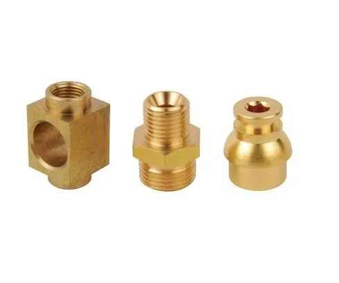
A thermowell is the simplest possible instrument part with a hidden problem. On the outside it is a tube with a closed end that goes into a process. On the inside it is a bore into which a temperature sensor goes, and the whole purpose of the part is to make that sensor read the process temperature instead of reading something else. Every dimension on this part is therefore either about holding pressure or about moving heat – and there is one dimension, the insertion depth, that controls the accuracy directly.
This is worth stating plainly because the drawing for a thermowell usually looks like a tube and a thread, and both of those are the easy part.
The one dimension that decides the accuracy: insertion depth
The sensor sits inside the thermowell rather than in the fluid. That protects the sensor, and it costs accuracy, because the temperature the sensor sees is not the process temperature. It is the temperature somewhere between the process temperature and whatever the outside of the thermowell is exposed to.
The error has two parts, and they behave differently:
- Axial conduction along the wall. Heat flows along the wall of the well from the hot process end toward the cool mounting end. This is a conduction error, and it increases with the sensor’s depth into the well. A sensor at the tip of a deep well reads significantly cooler than the process. This is the dominant error on most installations, and it scales roughly with the sensor’s immersion depth measured from the process end.
- Convection from the outside. The outer surface of the thermowell is in contact with ambient air or insulation or a vessel wall, and it will tend toward that temperature. A well that is exposed to ambient on a long length will conduct that ambient temperature inward. This is why the outside diameter matters and why a well with a large OD in a long installation reads worse than a slim one, even at the same insertion depth.
So the two dimensions that govern accuracy are the sensor insertion depth measured from the process-side face, and the wall thickness and outside diameter that set the conduction area. Both are ordinary dimensions on the drawing and neither is usually treated as an accuracy driver. On a thermowell specified to a stated accuracy class, they need to be, and they also need to be coordinated with the sensor: the sensor’s own specified insertion depth from its datasheet is what sets the thermowell’s internal depth, and where the two are specified by different parties on different documents, mismatches are the normal result.
What the thermowell protects the sensor from
Understanding what this part is protecting against explains a lot of its geometry, and it is why two thermowells that look similar can be very different.
- Corrosive or abrasive process fluid. This is the primary reason the part exists. The sensor is expensive and often not chemically compatible with the process; the thermowell isolates it completely.
- Pressure. A well in a pressurised vessel is a pressure boundary, and it is a pressure boundary regardless of how small it is. The wall, the closed end, and the thread all carry pressure loads, and the material has to be rated for it.
- High velocity flow. A sensor in a fast flow can be damaged, and a thermowell can also be eroded. On liquid service, immersion depth is often limited by vortex-induced vibration, and the well’s diameter and material both affect whether it will survive.
- Electrical noise or ground potential. A thermowell electrically isolates the sensor from the process, which matters where the process is at a ground potential the instrument cannot tolerate.
- Explosive or classified atmospheres. Where the well isolates a spark from the process, the well’s integrity – including its thread and any seal – is part of a safety function.
Each of these has a consequence for the drawing. Corrosion resistance picks the grade. Pressure picks the wall and the thread standard. Flow velocity picks the diameter and often a material with a fatigue allowance. Electrical isolation and classified service pick the seal and the joint treatment. So a thermowell’s specification is a combination of a pressure part, a corrosion part, and an accuracy part, and it is unusual in that the accuracy requirement can be the hardest of the three to satisfy because it is set by how long the heat has to travel.
The closed end, which is where the pressure and the accuracy meet
The tip of a thermowell is a formed or machined dome or flat, and it is simultaneously the thinnest part of the pressure boundary and the place where the temperature gradient is steepest. Three notes:
- Tip thickness is a pressure calculation and a heat-flow calculation. A thicker tip holds pressure better but insulates, which adds to the conduction error. This is a genuine trade and it is one of the few places on a machined part where material thickness is chosen against accuracy rather than for cost.
- The inside of the tip must be smooth. It is the sensor’s contact point and often the sensor’s tip sits directly against it. Internal surface finish at the tip affects both the heat transfer and the contact. On a sensor that measures by contact – a thermocouple, a resistance element – this is a real specification and it is usually missed.
- Tip geometry affects fill and response. A flat tip gives good contact and slower response; a domed tip sheds faster and may make poor contact. On a process with fast transients, the tip’s shape is a deliberate choice about how much response versus how much durability.
The thread and the process connection
The thread is how the well enters the vessel or the pipe, and on a pressure service it is a pressure boundary as much as the tip is. Practical points:
- The thread standard determines the seal method, because a thermowell’s thread can seal on the thread (taper, BSPP with a bonded washer, NPT), on a gasket or O-ring under a face (parallel thread with a face), or via a separate welding or brazing operation. Each of those implies a different set of dimensions and a different inspection plan.
- Where the well is welded into a vessel, the weld is part of the pressure boundary and the material must be weld-compatible. This is a common reason 316L is specified as the L grade, since the low carbon resists sensitisation in the weld’s heat-affected zone.
- Thread length is often over-specified because the insertion depth is expressed as a length. It is worth separating the two: how deep the sensor goes into the process, and how long the thread is. They are independent and they get conflated.
- The thread’s position relative to the tip is the dimension that ties the accuracy to the assembly. If the thread is a fixed length and the tip must reach a specific depth, the two have to be coordinated, and on a retrofit into an existing vessel this is a real constraint.
Grade selection
Carbon steel, 304 and 316 stainless steel, aluminium and brass are all held for this route, and on a thermowell the grade is chosen by the process rather than by the machining.
- Carbon steel is fine for a benign, dry process at moderate temperature, and it is the economical choice. It must be protected: an uncoated steel well in a humid process will corrode from the inside and the corrosion product will insulate the sensor and shift its reading.
- 304 for fresh water, air, and general service.
- 316L for anything chloride-bearing, and specifically the L grade where there is any welding or heat input.
- Brass is occasionally used where a galling-resistant or non-sparking requirement exists, but it has poor high-temperature strength and should not be used on hot steam service.
- Aluminium is essentially never correct for a thermowell. It conducts poorly relative to the others, which degrades the accuracy, and it has poor corrosion resistance in many processes.
Two grade-dependent manufacturing notes: austenitic stainless steel is hard to machine and needs the tool discipline already described elsewhere in this section; and where the material is not stainless steel and not plated, the interior surface condition becomes a specification, because an uncontrolled inside surface on a carbon steel well will both corrode and thermally insulate.
Tolerance, allocated to accuracy and pressure
+/-0.02 mm general machining with tighter bands on the flagged dimensions is the workable framework, and on this part the flagged dimensions are almost all related to the tip and to the mounting face rather than to the outline.
- The distance from the process-side face to the sensor seat, held tightly, because this is the immersion depth and it is the accuracy. This should be measured from a defined face – the tip face, not the shoulder or the thread end, because a face that is machined later will move.
- Internal bore size and the sensor’s fit, as a clearance fit to the specified sensor, because a thermowell is designed around a particular sensor’s diameter.
- Tip thickness, as a real measured requirement rather than a nominal, since it is the pressure boundary.
- Internal surface finish at the tip and along the bore, specified with a convention and, on the contact area, with an inclusion callout.
- Thread class and fit per the applicable standard.
- External diameter along the immersion length, where the OD affects the conduction error and where a tapered OD would affect both the fit and the reading.
- Overall length and thread length at a general band, unless they carry a functional dimension.
Insertion depth is the one dimension on a thermowell you cannot sample
- Insertion depth, measured from the process face to the sensor seat, on every part. This is the one dimension that must not be sampled.
- Functional leak or pressure test on every part where the well is a pressure boundary. On a thermowell this is also the test that confirms the tip and the thread, which are the two places it fails.
- Tip thickness, by measurement rather than by process confirmation.
- Internal surface finish at the tip, inspected.
- CMM data on the critical dimensions with the dimensional report accompanying the first article, and every stage logged against the part number.
- Material certification with the grade and heat number, because on a corrosion service the grade is the whole point and it is the first thing questioned after a field failure.
The sensor, and what its datasheet requires
What is the sensor, and what does its datasheet say about its required immersion depth and its tolerance band? A thermowell is designed backwards from the sensor – the well’s internal depth, its bore, its tip thickness and its accuracy class all follow from what the sensor needs and how much error it tolerates. If the sensor is being chosen after the thermowell, the well is probably wrong. Bringing the sensor’s specification to the enquiry – even if it is still provisional, even if it is only the mounting thread and the required insertion depth – is worth more on this part than any other single piece of information, and it is the single most commonly omitted item on thermowell enquiries.
The CNC Machining Parts range is the parent for parts like this one; tooling logic, finishing options and tolerance notes for the whole family are gathered on its overview page.
Specifications
| Item | Stainless Steel CNC Machined Thermowell Bodies |
|---|---|
| Brand | AUNOV |
| Designing | Send drawings, or send a sample to be measured – DFM notes are returned before any tooling is cut; the approved drawing is kept as the controlled master. |
| Tooling | Tooling is designed and built in house and held under your part number, so the die stays dedicated to your part. |
| Samples | Sample and first article are the same discipline here: measured, reported, then approved. |
| Materials | Standard stock: carbon steel (SPCC / DC01), 304 / 316 stainless steel, aluminium, brass; grade and temper are confirmed in writing before tooling. |
| Surface finish | Plating, coating, anodising or passivation are chosen from the drawing; masking and laser marking are available where the job needs them. |
| Processing | Turning, milling and drilling sequenced to minimise handling and re-chucking; every stage is logged against your part number. |
| Equipment | 12 CNC turning centres with automatic bar feeders; first articles and batch samples are checked on the CMM. |
| Tolerance | +/-0.02 mm general machining, tighter on flagged dimensions; critical dimensions carry CMM data with the shipment. |
| Delivery terms | CIF or DDP, with FOB available, T/T or L/C, with D/P accepted on repeat business; each volume tier carries its own quoted price. |
Related Products


Request a Quote for This Part
Send a drawing or sketch — get material advice, tooling cost and a per-piece price within 24 hours (working days).