
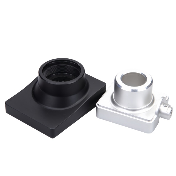
The boss on a mounting base exists to position and support—its height and diameter are functional dimensions
An aluminum square mounting base with machined bosses—a plate with raised cylindrical or rectangular pads—is the foundation component for motors, sensors, pumps, and optical assemblies. The bosses serve two functions: they set the mounted component’s height (the boss height is the dimension that locates the component in the assembly’s Z axis) and they stiffen the local area where fastener clamp load concentrates (a boss under a bolt head turns a bending load on a thin plate into a compression load on a thick column).
We machine boss heights to ±0.05 mm as standard (±0.02 mm on request for instrument bases where the component stack’s height budget is tight). The height is measured from the base’s bottom face—the assembly datum—so the base’s own flatness adds directly to the height error. A base that is flat within 0.05 mm and has bosses at ±0.05 mm delivers component height within ±0.1 mm total; optical stack designs need both numbers tightened to hit ±0.03 mm overall.
Boss wall thickness and fillet: the transition where bosses crack
Each boss meets the base plate at a fillet. This fillet carries the bending moment that a side-loaded component transmits through the boss into the plate. A sharp or shallow fillet (R < 1 mm) concentrates stress (Kt > 3) and cracks under cyclic load; we machine a minimum R2 fillet at every boss-plate junction on our standard bases and R3 for bases that carry side-loaded components (pumps with heavy side-tube loads, motors with belt tension).
Boss inside diameter matters as much as the outside: a boss bored for a dowel or bearing must leave enough wall under the bore to carry the press-fit expansion. We keep a minimum 0.15× bore diameter of wall between bore and boss OD (e.g., a 20 mm bore gets at least 3 mm wall), below which the boss splits during press-in—usually at assembly, occasionally in service, always expensively.
Fastener bosses vs. plain plate: threading into aluminum has engagement limits
A boss bored and tapped for a screw (rather than through-bolted) must provide enough thread engagement in the aluminum to develop the screw’s strength. Aluminum needs roughly 2× the screw diameter in engagement to match a steel screw’s tensile capacity (vs. 1× in steel). A 6 mm screw needs 12 mm of engaged aluminum thread, which requires a boss of at least 12 mm height plus the drill point allowance.
Where the boss height can’t deliver full engagement, we recommend and install threaded inserts (helical coil or key-locking) that put a steel thread in the aluminum boss—an insert with 1.5× D engagement in aluminum restores full screw strength. On repeated-assembly bases (fixtures, serviceable equipment), inserts are our default regardless of engagement math, because bare aluminum threads strip after 5–10 assembly cycles while an insert’s steel thread survives hundreds.
Base flatness and the surface it bolts to: two flat surfaces still need a datum strategy
A mounting base bolts to a machine frame, and the component bolts to the base. The base’s contribution to alignment error is its own flatness (both faces) plus the parallelism between its top (boss) face and bottom face. We machine both faces in setups referenced to the same datum (bottom face first as the primary datum, bosses machined from that datum), holding face parallelism within 0.03 mm.
In the assembly, the base’s bottom face conforms to whatever it bolts to: a base bolted to a warped frame flexes to match it (a 60 mm-wide aluminum base will conform to frame warp up to ~0.1 mm without shimming, with bolt load doing the bending). When the frame is worse than that or the design can’t tolerate the conforming stress, the installation sheet we provide specifies the frame flatness requirement: 0.05 mm over the base’s footprint is the number that keeps the base’s delivered accuracy intact.
Finish selection for aluminum bases: anodize is usually right, but not on threaded bosses
Clear or black Type II anodize (15–20 µm) is the default finish for aluminum mounting bases: it hardens the surface against scratch damage during repeated component mounting, and it looks right on industrial equipment. But anodize on a tapped hole changes the thread’s effective size (anodize builds ~half its thickness into the bore: 8–10 µm on a diameter) and its insulating, high-friction surface on threads both binds and interferes with grounding paths.
Our standard practice: mask all tapped holes before anodizing (silicone plugs in production), leaving bare, conductive, correctly-sized aluminum threads. Unmasked-anodized threads are the most common defect we see in competitors’ bases—the screw galls on first assembly in the anodized thread, or measures a thread class looser after the coating’s thickness is accounted wrong.
How we verify square mounting bases before shipping
- Flatness: Both faces on a granite plate, feeler/indicator: 0.05 mm standard; parallelism top-to-bottom 0.03 mm.
- Boss dimensions: Height (from bottom datum, depth micrometer on a surface plate: ±0.05 mm standard), OD (caliper/micrometer), bore size (plug gauge), boss-to-boss position (CMM on first article; production: gauge pins in two bores, measured span).
- Fillets: Radius gauge at each boss root on first article; visual on every part for undercutting or tool marks at the root.
- Threads: Go/no-go per class on 100 %; torque test one screw per batch to 1.5× assembly torque into a masked (bare) thread hole.
- Finish: Anodize thickness (eddy current, first article + sample), thread mask verification (a screw gauge feels bare aluminum in a masked hole), visual for uniform coverage.
The CNC Machining Parts range is the parent for parts like this one; tooling logic, finishing options and tolerance notes for the whole family are gathered on its overview page.
Specifications
| Item | Aluminum Square Mounting Bases with Machined Bosses |
|---|---|
| Brand | AUNOV |
| Designing | Share your print, or send a part to be measured, our engineers reply with a manufacturability assessment and pricing. |
| Tooling | Tooling designed and cut in house, held under your part number. |
| Samples | Approval samples ship with a full dimensional report and material certification. |
| Materials | Stock for this part leads with aluminium, alongside carbon steel (SPCC / DC01), 304 / 316 stainless steel, brass and copper, and the grade is fixed at the drawing review. |
| Surface finish | Zinc, nickel or chrome plating, e-coat, powder coat, anodising or passivation, as called out on your print. |
| Processing | Progressive deep draw stages with in-line annealing as the draw ratio demands, with piercing and finish machining under the same roof. |
| Equipment | Our press floor runs 5-250 T mechanical and 250-500 T hydraulic presses, CNC turning centres and a climate-controlled CMM room. |
| Tolerance | +/-0.1 mm on as-drawn features, +/-0.03 mm after machining. |
| Delivery terms | FOB as standard, DDP available for EU and US destinations, T/T or L/C, D/P on repeat business, call-off schedules and blanket orders supported. |
Related Products


Request a Quote for This Part
Send a drawing or sketch — get material advice, tooling cost and a per-piece price within 24 hours (working days).