
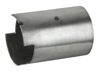
A fuel pump casing is a sealing problem with a motor inside
Where a fuel pump housing is the fuel-wetted shell that holds the stator and bearing, a fuel pump casing is usually the outer enclosure that closes the assembly – the part that takes the end cap, forms the pressure boundary, and carries the return passages or the mounting collar in an in-tank module. The design priorities are different: the casing is judged by how it closes, how it holds pressure or at least holds fuel, and how it survives being assembled and tested on a high-rate line.
We draw casings from 1.4301 or 1.4404 stainless steel, or from coated steel where cost dominates and the fuel contact is incidental. The drawing is a straightforward shell, but the closing features – crimp grooves, weld lips, O-ring seats, snap rims – are where the engineering lives.
How the casing closes: crimp, weld, or swage
Three closure methods dominate, and the casing geometry must be designed for exactly one of them:
| Crimp | A rolled or coined groove in the casing wall is folded over the cap flange. Fast, high-volume, and repairable-free by design. Needs a crisp groove profile and a controlled wall thickness at the groove so the crimp does not crack. |
|---|---|
| Laser weld | A lapped or butt joint between casing and cap is fused. Gives the best leak margin but demands a clean, square, oxide-free seam and a fit-up gap under ~0.1 mm. |
| Swage / spin | The casing rim is spun or swaged over the cap. Suits round casings and gives a smooth external profile; the metal must be ductile enough not to tear at the rim. |
We hold the groove depth, width, and wall thickness at the groove so the customer’s crimp tool behaves predictably. A crimp groove that is 0.05 mm too shallow will not hold; one that is too deep cracks the wall on the second forming pass. Getting these dimensions right is what turns a casing from a leak problem into a non-event.
Leak paths and how we design them out
When a fuel module leaks, the leak is almost never through the metal – it is along an interface. The interfaces a casing defines:
- Casing-to-cap joint. The dominant leak path. Addressed by the closure method above plus a sealant or an elastomeric gasket where specified.
- Terminal feed-throughs. Where the pump leads exit, the seal is usually a moulded header bonded to the cap, not the casing, but the casing must provide a concentric, burr-free seat for that header.
- Mounting collar to tank flange. If the casing carries the module’s retention collar, the O-ring seat there must be smooth and concentric, or fuel weeps past the module under slosh.
We inspect for burrs on every sealing-adjacent feature; a 0.05 mm burr on a header seat is enough to create a slow leak that only shows up as a fuel smell in a hot garage.
Wall thickness, stiffness, and crush resistance
A casing in an in-tank module is not usually a pressure vessel, but it does see compressive and impact loads during handling and during a collision. Two rules keep it robust without wasting material:
- Thickness at the closure is set by the closure method, not by pressure – a crimp needs local thickness to resist cracking, a weld needs a thin, clean edge to fuse cleanly.
- Thickness in the barrel is set by stiffness against handling crush. For a 30-50 mm diameter casing, 0.6-1.0 mm stainless steel is typical; thinner works but the casing dents in the plant.
We keep the wall as uniform as the process allows so there are no thin spots at the groove or rim, which is where cracks initiate under vibration.
The casing as a manufacturing and test interface
Because the casing closes the module, it also defines how the module is assembled and tested:
- Location features for the assembly fixture – a datum diameter, a shoulder, or a notch that the automation clamps on. Without these, the plant invents a fixture that grips the sealing surface and damages it.
- A test port or a sealed test volume, if the module is leak-tested. We can form a port or a flat for a test fitting on request.
- Identification – laser marking on the casing wall, or a formed flat that takes a label, so the module can be traced. We prefer a formed flat because a label on a curved surface peels.
Material selection for fuel contact
Casing material is driven by the same fuel chemistry as the housing – ethanol content, water absorption, temperature. Stainless Steel 1.4404 is the safe choice for flex-fuel; 1.4301 is adequate for gasoline and diesel. Coated steel is viable when the internal surface is protected and the casing is not the primary fuel-wetted boundary. Where the casing touches the tank structure, we consider the material pairing to avoid galvanic corrosion over a fifteen-year service life.
Forming the crimp groove in the die, where volume justifies it
Can you form the crimp groove in the die?
Yes, in the same progressive die where volume justifies it; for lower volume, the groove is formed in a secondary station. Either way the groove dimensions are a controlled characteristic.
How tight is the weld fit-up you can supply?
We hold the weld lip and the cap seat so the fit-up gap stays under 0.1 mm; larger gaps force the customer to add filler and risk a porous weld.
Do you leak-test the casing?
Where the casing is itself a boundary, yes, as a lot-acceptance air-decay test. Where the seal is made at assembly, the test belongs at the module level – we supply the dimensions that make it repeatable.
What about fuel slosh noise?
A casing with an integral baffle or a formed rib can damp slosh; the rib is a low-cost die feature and often removes the need for a separate baffle part.
Specifying a fuel pump casing
Send the closure method (crimp, weld, or swage), the cap interface, the sealing features and their tolerances, the fuel type and temperature, the mounting and fixture features, and the annual volume. With those, we can quote a casing whose closure behaves, whose seals do not leak, and whose wall survives the plant – which is what a casing is actually judged on.
This part belongs to our Automotive Motor Components range. The automotive motor components pages collect the process notes, common materials and inspection points behind every product in the family.
Specifications
| Item | Fuel pump electric motor casing |
|---|---|
| Brand | AUNOV |
| Designing | Your drawing sets the part – samples are reverse-measured into a controlled drawing; revisions are re-quoted once rather than silently absorbed. |
| Tooling | Our toolroom covers die design, wire-cut EDM and maintenance, so the die charge appears as its own quotation line, and the charge is refundable against agreed volumes. |
| Samples | Samples are issued for approval before the run, so the part is proven before it is made in volume, and the signed sample is kept for future reorders. |
| Materials | Carbon steel, 304 / 316 stainless steel, aluminium and brass are held in stock; the drawing review fixes the final grade. |
| Surface finish | Zinc / nickel / chrome plating or e-coat, chosen for the environment this housing sees; salt-spray tested to drawing. |
| Processing | Parts are deep drawn from coil or blank with in-process annealing so the walls thin evenly, then trimmed, pierced, formed and finished. |
| Equipment | 5-250 T mechanical and 250-500 T hydraulic presses, annealing ovens, and CNC turning and machining centres for secondary work. |
| Tolerance | +/-0.05 mm on controlled dimensions and +/-0.1 mm on general features; capability studies supplied on request. |
| Delivery terms | CIF or DDP, with FOB available, payment by T/T or L/C, quoted in USD or EUR; repeat orders reuse the approved first article. |
Related Products


Request a Quote for This Part
Send a drawing or sketch — get material advice, tooling cost and a per-piece price within 24 hours (working days).