
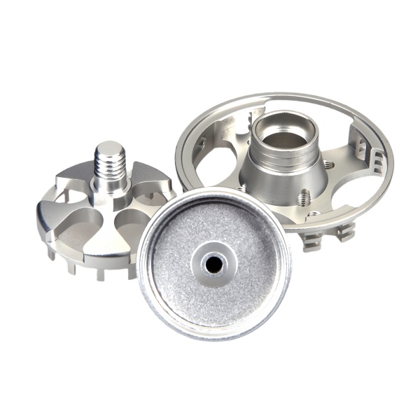
Impeller wheel balance quality directly determines pump vibration, noise, and bearing life
An aluminum impeller wheel—rotating at speeds from 1,000 to 30,000 RPM depending on the application—generates centrifugal force at its bearings proportional to its mass unbalance. Even 1 gram of unbalance at 50 mm radius produces 500 g·mm of unbalance moment; at 10,000 RPM this generates a rotating force of over 540 N—more than the weight of the entire pump.
We balance impellers to ISO 21940 grade G6.3 as standard (G2.5 for speeds above 5,000 RPM or for pumps with noise specifications). For a 1 kg impeller at 3,600 RPM, G6.3 corresponds to a permissible residual unbalance of 6.3 × 1000 / (2π × 60) ≈ 16.7 g·mm. Correction is by material removal (drilling or milling shallow pockets on the back face, 180° from the heavy spot) or occasionally by material addition (epoxy balancing compound in a recess, for impellers where drilling would weaken the blades). We record the correction mass, location, and residual unbalance for each impeller in the batch record.
Blade profile accuracy determines the pump’s flow-head curve more than the impeller diameter does
The shape of the impeller blades—their inlet angle, outlet angle, and the curvature between—determines the theoretical head (pressure rise) the pump can generate at a given flow rate. The classic Euler equation for a centrifugal impeller shows that head is proportional to the tangential velocity change across the blade passage: H = (u₂c₂u – u₁c₁u) / g. The blade outlet angle β₂ sets c₂u and therefore dominates the head-flow characteristic.
A blade outlet angle that deviates 2° from design (easily caused by tool deflection during 5-axis milling of thin blades) changes the pump’s shutoff head by roughly 3–5 % and can shift the best-efficiency point along the flow axis. For a pump specified to deliver 25 m head at 40 m³/h with ±5 % tolerance, a 3° blade angle error consumes the entire tolerance band. We machine blades with a ballnose end mill taking light finishing passes (0.2 mm depth) in a climb-milling direction to minimize deflection, and we verify the blade profile on the first article using a CMM with a stylus scanned along the blade pressure surface at three radial positions.
Cover (shroud) clearance to the casing determines internal leakage—the pump’s volumetric efficiency
An impeller cover—the front shroud that encloses the blade tips on the suction side—runs with a small axial clearance (typically 0.1–0.3 mm) relative to the pump casing’s wear ring or sealing face. This clearance controls the internal leakage from the discharge side back to the suction side: fluid at discharge pressure slips through the clearance instead of exiting through the outlet port.
The leakage flow is proportional to clearance cubed (approximately, for laminar flow through an annular gap). Increasing the clearance from 0.1 mm to 0.2 mm (a 2× change) increases the leakage roughly 8×, which can reduce volumetric efficiency from 95 % to 80 % on a low-specific-speed impeller. We hold the cover’s sealing face flat and perpendicular to the bore within 0.01 mm and machine the impeller’s axial length so the assembled clearance falls in the middle of the specified range (accounting for the casing’s tolerance, which the customer provides or we measure on a sample casing).
Material choice for impeller and cover: 6061 vs. 7075 vs. 2024 aluminum
Most aluminum impellers use 6061-T6 as the baseline. Higher-strength alloys are selected when stress or fatigue calculations demand them:
- 6061-T6: Yield 276 MPa. Excellent corrosion resistance (no SCC risk in any environment). Good weldability and anodizability. The default for impellers below ~100 m/s tip speed and covers for all applications.
- 7075-T6: Yield 503 MPa—nearly 2× 6061. Required when tip speed exceeds ~100 m/s (centrifugal stress scales with tip speed squared) or when the impeller sees frequent pressure pulses (cavitation) that fatigue the blade roots. Not weldable and more expensive (~30–50 % over 6061). SCC risk in the T6 temper for thick sections; specify T73 for stress-corrosion-critical applications.
- 2024-T351: Yield 325 MPa, better fatigue strength than 6061. Excellent for covers subject to cyclic pressure loading (the cover flexes once per blade-passing event). Corrosion resistance is poorer than 6061 (requires cladding or anodize for corrosive environments).
How we validate an impeller-and-cover assembly before shipping
Complete validation sequence:
- Dimensional audit: Impeller: bore size (H6/H7), overall axial length, blade profile sample check, seal face flatness and perpendicularity. Cover: bore, face flatness, sealing surface finish.
- Assembly clearance check: Impeller mounted on a master shaft, cover installed with the specified gasket/shim; axial clearance between impeller seal face and cover measured with a feeler gauge or dial indicator. Acceptance: within the drawing-specified range (typically 0.1–0.3 mm).
- Dynamic balance: Impeller (with cover, if the cover rotates with the impeller) balanced on a dynamic balancing machine at 500–1,000 RPM test speed. Correction as described. Acceptance: residual unbalance within G6.3 or specified grade.
- Spin test (high-speed impellers): For impellers above 5,000 RPM rated speed, a spin test at 110 % rated speed for 5 minutes confirms that the impeller does not burst or deform. After the test, re-verify bore size and balance (change < 5 % from pre-test).
- Performance test (sample, if specified): One assembly per batch installed in a hydraulic test loop; flow-head curve measured at 5 points. Acceptance: head within ±5 % and flow within ±3 % of the drawing-specified duty point. This test is the ultimate verification that the impeller geometry (not just the dimensions) meets the hydraulic design intent.
Sizing the draw for a part like this — reduction per station, ironing allowance, flange width — is covered step by step in our deep drawn covers guide.
Specifications
| Item | Aluminum CNC Machined Impeller Wheels and Covers |
|---|---|
| Brand | AUNOV |
| Designing | Send drawings, or send a sample to be measured, DFM feedback is returned with the quote. |
| Tooling | Our own toolroom designs and builds every die, with your part number on the tool record. |
| Samples | Sample parts arrive with dimensional data and material certs. |
| Materials | Stock for this part leads with aluminium, alongside carbon steel (SPCC / DC01), 304 / 316 stainless steel, brass and copper, with grade selection confirmed at drawing review. |
| Surface finish | Plating, e-coat, powder coating, anodising or passivation, selected against the drawing requirement. |
| Processing | Progressive deep draw stages with in-line annealing as the draw ratio demands, then pierced and CNC-machined in house. |
| Equipment | Mechanical presses 5-250 T, hydraulic presses 250-500 T, in-house CNC cells and a temperature-controlled inspection room. |
| Tolerance | Drawn tolerances held to +/-0.1 mm, +/-0.03 mm on machined features. |
| Delivery terms | Standard terms FOB, DDP offered to EU and US, T/T and L/C; D/P on repeat accounts, call-off scheduling supported. |
Related Products



Request a Quote for This Part
Send a drawing or sketch — get material advice, tooling cost and a per-piece price within 24 hours (working days).