
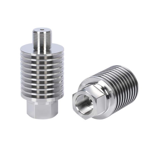
Finned fitting heat transfer is set by fin surface area and the fin root thickness, not by fin count alone
A machined finned heat sink fitting—a threaded fitting with integral cooling fins—removes heat from a fluid passing through it (or from a component it’s threaded into). The fins exist to add surface area for convection. But adding fins only helps while each fin stays thermally connected to the base: as fins get thinner and more closely spaced, the conduction path from fin root to tip becomes the bottleneck, and the outer portions of tall, thin fins contribute almost nothing.
The engineering metric is fin efficiency: the ratio of actual heat dissipated to what the fin would dissipate if its entire surface were at root temperature. For a stainless steel fin (low conductivity, 16 W/m·K), a 15 mm tall × 1.5 mm thick fin has an efficiency of roughly 0.45—more than half the fin’s surface is wasted. The same geometry in aluminum (205 W/m·K) achieves ~0.9. We therefore keep stainless steel fins short and thick (8–12 mm tall, 2–3 mm thick, spaced 4–6 mm apart) and compensate with more fins around the circumference rather than taller ones. When a customer needs substantially more dissipation than stainless steel fins can provide, we recommend brazing aluminum fins to a stainless steel fluid-wetted base: the stainless steel handles the fluid and the aluminum does the heat rejection.
The fin-to-base fillet is where thermal and mechanical stress both concentrate
Each fin meets the fitting body at a root that must conduct heat and carry the fin’s bending load (fins get bumped during handling and installation). A sharp root (R < 0.3 mm) both restricts heat flow (contact area at the thermal choke point) and concentrates mechanical stress (Kt > 3 under lateral fin load).
We machine fin roots with a full-radius form tool that leaves an R1–R2 mm fillet where the fin blends into the body. The form tool cuts the entire fin profile—root radius, flank, and tip radius—in one pass, keeping all fins on a fitting geometrically identical, which matters for balance if the fitting is on a rotating component and for appearance on visible installations. Tip edges get a 0.3 mm break so the fins are not finger-cutters during installation.
Thread seal at the heat sink fitting must survive thermal cycling without relaxation
A finned fitting threads into a component that cycles in temperature—the whole point of the fins is that heat flows through the joint. The thread’s seal (whether a dryseal thread, a gasket, or an O-ring boss) sees this cycling too, and seal relaxation over cycles is the dominant failure mode.
Dryseal threads relax as the threads’ contact points creep under cyclic load; we avoid relying on a dryseal thread alone above 80 °C service. O-ring boss seals handle cycling better if the O-ring material is chosen for the temperature range: nitrile to 100 °C, fluorocarbon (FKM) to 200 °C. Metal gaskets (soft copper or aluminum crush washers) actually improve through the first several cycles as they conform, then stabilize—our default for finned fittings in steam or hot-oil service. We specify a new crush washer at every re-assembly; a re-used washer’s residual compression is unpredictable.
Material selection for finned fittings: 316 vs. brass for the dissipation-versus-corrosion trade
Brass conducts heat 7–8× better than stainless steel, so a brass finned fitting of identical geometry dissipates substantially more heat. Yet most finned fittings we machine are stainless steel because the fluid environments (hot water, steam, chemical lines) attack brass:
- 316 stainless steel: For any chloride-bearing or chemically aggressive fluid; hot water systems, food process lines, marine. Poor thermal performance requires more fin area—larger fitting or more fins—to match brass.
- Brass (C36000): For closed-loop hot water and hydronic heating (non-aggressive, oxygen-free water), where brass’s conductivity halves the required fin count. Not for chlorinated water or ammonia-bearing fluids.
- Nickel-plated brass: A compromise for mildly aggressive fluids where plating protects the brass—though any scratch in the plating at a thread becomes a dezincification site.
How we verify a finned fitting before shipping
- Dimensional: Thread class (go/no-go), fin OD, overall length, fin count and spacing (first article + every 25th part).
- Thermal performance (sample, if specified): One fitting per batch in a calibrated thermal rig—fluid at controlled temperature through the bore, the finned exterior in still air—measuring steady-state heat rejection. Acceptance: within ±10 % of drawing-specified dissipation.
- Pressure test: 1.5× rated pressure, 10 minutes, at the maximum service temperature if the fitting is rated above 100 °C (hot testing catches seal relaxation that a room-temperature test misses).
- Fin integrity: Each fin nudged with a 10 N lateral force at the tip; no movement or cracking. This catches machining cracks at fin roots that a visual check can miss.
This part sits inside our CNC Machining Parts range. Across the cnc machining parts pages you will find the process notes, common materials and inspection points behind every product in the family.
Fin efficiency versus fin count
A finned fitting sheds heat in proportion to fin area, but each added fin also blocks airflow and adds weight, so there is a point where more fins cools less, not more. We set the fin count and height from the fluid temperature and the available airflow rather than from a maximum, and we keep the fin-to-base fillet generous because that is where the heat actually crosses. A fitting with the right fin does more with less metal, and it is lighter and cheaper to machine than one buried in fins that the air cannot reach. The thermal math drives the geometry, not the other way around.
Cleaning access for fouled fins
Fins collect scale and debris in service, and a fitting that cannot be cleaned stays fouled, so we design the fin pitch and the base so a brush or a flush reaches the root. Where the fluid is dirty we open the pitch at the cost of some area, because a clean fin at lower count beats a choked fin at higher count. We note the cleaning method on the drawing so maintenance plans for it instead of discovering the fins are unreachable after the first season.
Specifications
| Item | Stainless Steel CNC Machined Finned Heat Sink Fittings |
|---|---|
| Brand | AUNOV |
| Designing | Send drawings, or send a sample to be measured, DFM feedback is returned with the quote. |
| Tooling | Every die designed and built in our toolroom, held under your part number. |
| Samples | First-article samples ship with dimensional data and material certs. |
| Materials | 304 / 316 stainless steel is the primary stock for this part, alongside carbon steel (SPCC / DC01), aluminium, brass and copper, with the final grade confirmed at the drawing review. |
| Surface finish | Plating, e-coat, powder coating, anodising or passivation as the drawing calls out, per the drawing. |
| Processing | Staged deep drawing with in-line annealing where needed, then pierced and machined in house. |
| Equipment | Our press floor runs 5-250 T mechanical and 250-500 T hydraulic presses, CNC turning centres and a climate-controlled CMM room. |
| Tolerance | +/-0.1 mm on as-drawn features, machined features held to +/-0.03 mm. |
| Delivery terms | FOB standard, DDP offered for EU and US, T/T or L/C, D/P on repeat business, call-off scheduling supported. |
Related Products


Request a Quote for This Part
Send a drawing or sketch — get material advice, tooling cost and a per-piece price within 24 hours (working days).