
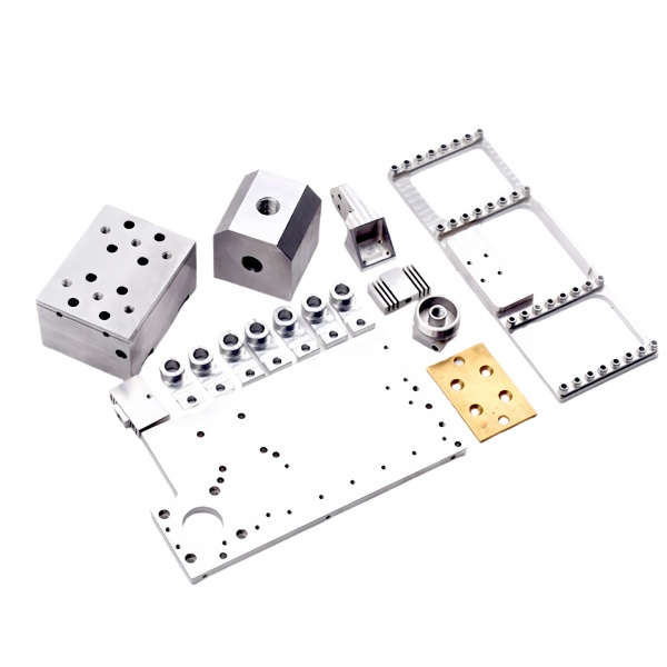
Plate stiffness-to-weight ratio is the primary reason for choosing aluminum over steel in mounting brackets
An aluminum mounting bracket or frame plate achieves roughly 1/3 the weight of an equivalent steel plate at the same stiffness—because aluminum’s Young’s modulus (69 GPa) is about 1/3 that of steel (200 GPa), but its density (2.7 g/cm³) is also about 1/3 that of steel (7.85 g/cm³). The ratio E/ρ (specific modulus) is nearly identical: ~25.5 GPa/(g/cm³) for aluminum vs. ~25.5 GPa/(g/cm³) for steel. This means that for a bending-limited design (where deflection, not strength, governs the thickness), an aluminum plate can be made 3× thicker than a steel plate of the same weight—and because bending stiffness scales with t³, the aluminum plate will be 3× stiffer than the steel plate at equal weight.
The practical outcome: for a bracket that must deflect less than 0.1 mm under a 50 N load across a 100 mm span, a 3 mm steel plate weighs about 235 g while a 9 mm aluminum plate weighs about 243 g (essentially the same weight) but deflects only 0.004 mm versus the steel plate’s 0.10 mm—a 25× improvement in stiffness at essentially no weight penalty. This is why aluminum dominates structural frames and mounting brackets in aerospace, robotics, and portable equipment where both weight and rigidity matter.
Hole position tolerance on the plate determines whether the mounted component aligns with the rest of the assembly
A mounting plate’s function is to position one component relative to another (or relative to a reference datum). The hole pattern on the plate is the physical embodiment of that positioning, and its accuracy directly determines the assembled system’s alignment quality.
We hold hole positions to true position tolerances that reflect the application:
- General mounting: ±0.15 mm diameter zone at MMC. Suitable for bolts with standard clearance (M5 bolt in 5.5 mm hole = 0.25 mm clearance). Most industrial equipment falls into this category.
- Precision alignment: ±0.05 mm diameter zone at MMC. Required when the mounted component has tight positional requirements relative to other components (optical mounts, sensor targets, shaft couplings). Achieved by boring or reaming holes after the plate profile is finished, using the plate’s datum features as reference.
- Locating / dowel applications: ±0.02 mm diameter zone. Used for dowel pins that establish the primary datum relationship between two components. Requires grinding or jig-grinding of the hole to achieve this level of positional accuracy. Cost: 2–3× general mounting due to extra operation and inspection time.
Frame corner joints determine whether the welded or fastened structure behaves as a rigid body or a mechanism
When a machined plate serves as one side of a frame (with other plates or extrusions joining at the corners), the behavior of those corner joints under load determines whether the frame acts as a rigid structure or as a flexible four-bar linkage. A rigid corner transmits moment (bending force) from one side to the next; a flexible corner allows relative rotation between sides.
We evaluate three common joint types for aluminum frames:
- TIG-welded corner: Full-penetration TIG weld with filler rod (ER4043 or ER5356). Produces a joint with 80–100 % of the base metal’s stiffness. The heat-affected zone (HAZ) extends 10–20 mm from the weld line and may reduce local yield strength by 20–30 % in 6061-T6 (the T6 temper is partially annealed by welding heat). Post-weld heat treatment can restore some strength but adds cost and distortion risk. Best choice for permanent frames where maximum rigidity is required and disassembly is not anticipated.
- Riveted corner: Solid aluminum rivets (AN470 or equivalent) or blind rivets (pop rivets) through overlapping flanges. Joint stiffness depends on rivet diameter, spacing, and hole fit. Typical riveted frame corners achieve 40–60 % of welded-joint stiffness. Advantages: no heat input (no HAZ), disassembleable, lower skill requirement than welding. Best for frames that may need modification or repair in the field.
- Bolted corner with fitted pins: Precision-ground dowel pins in reamed holes plus clamping bolts. Achieves 70–90 % of welded stiffness if the pins are interference-fit and the bolts are properly torqued. The most expensive option (requires precision machining of holes and purchase of ground pins) but offers the best combination of stiffness, adjustability, and serviceability. Used in precision equipment frames where thermal expansion compensation or periodic realignment is needed.
Surface treatment selection for aluminum plates affects corrosion resistance, appearance, and electrical conductivity
Aluminum forms a natural oxide layer (Al₂O₃, 2–5 nm thick) that provides basic corrosion protection but is insufficient for outdoor or harsh-environment service. Surface treatments enhance this protection and add functional properties:
- Type II anodize (sulfuric acid): 10–25 µm oxide layer. Provides excellent corrosion resistance (1000+ hours salt spray for 20+ µm thickness). Can be dyed any color (or left natural/silver). Slightly reduces electrical conductivity (oxide is insulating). Default choice for most aluminum plates and frames unless electrical grounding is required.
- Type III hard anodize: 25–50 µm oxide layer, hardness 400–500 HV (comparable to case-hardened steel). Excellent wear resistance for sliding or contact surfaces. Dark gray to black color (cannot be brightly dyed). Reduces fatigue strength by 10–20 % due to surface stress from the anodizing process. Used for wear plates, guide surfaces, and frames subject to abrasion.
- Chromate conversion coating (Alodine/ Iridite): Thin (0.5–3 µm), yellow or clear appearance. Provides good corrosion resistance for indoor use and serves as an excellent paint/adhesive primer. Preserves electrical conductivity (thin enough for grounding applications). Low cost (~0.01 USD/dm²). Used for electronic enclosures, EMI shielding frames, and any aluminum part that must be electrically grounded.
- Powder coat: 60–80 µm polymer coating over chromate conversion primer. Available in any color. Durable and decorative. Adds significant thickness (must account for in fits and clearances). Not suitable for precision-machined surfaces where dimensional change cannot be tolerated. Used for visible exterior frames and consumer-product housings.
How we verify that a batch of aluminum plates meets the customer’s flatness and dimensional requirements before shipping
Every batch of aluminum plates, frames, and brackets receives:
- 100 % dimensional inspection: All critical dimensions measured per the drawing. For high-volume orders (>100 parts), we use SPC sampling (every 10th part full inspection, every part go/no-go on critical features).
- Flatness verification: Plate placed on a granite surface plate; feeler gauge measures gap at worst location. Acceptance: gap ≤ specified flatness (typically 0.1 mm/m for general plates, 0.02 mm/m for precision mounting plates). Plates exceeding flatness limit are straightened (if possible without marring cosmetic surfaces) or scrapped.
- Surface treatment verification: Anodized parts: dye spot test confirms seal integrity; thickness measurement (eddy current or micrometer) confirms layer thickness within spec. Chromate-coated parts: copper sulfate spot test confirms coating presence; salt spray sample (one per batch) confirms corrosion resistance.
- Material certification: Mill test report confirming 6061-T6 or specified alloy/temper. For aerospace or medical applications, additional chemical analysis (ICP-OES) on one sample per heat lot.
- Packaging: Aluminum plates are interleaved with foam or VCI paper to prevent scratching during transit. Large frames are crated with custom-cut foam inserts. Every shipment includes a packing list identifying each part number and quantity.
The CNC Machining Parts range is the parent for parts like this one; tooling logic, finishing options and tolerance notes for the whole family are gathered on its overview page.
Specifications
| Item | Aluminum CNC Machined Plates Frames and Mounting Brackets |
|---|---|
| Brand | AUNOV |
| Designing | Send the drawing, or a bracket sample we can measure, the quotation comes back with a manufacturability review attached. |
| Tooling | Our own toolroom designs and builds every die, held under your part number. |
| Samples | First-off samples are sent with a dimensional report and material certificate. |
| Materials | Aluminium leads the stock list for this part, alongside carbon steel (SPCC / DC01), 304 / 316 stainless steel, brass and copper, and the grade is fixed at the drawing review. |
| Surface finish | Finish options: plating, e-coat, powder coating, anodising or passivation, fixed at the drawing review. |
| Processing | Deep drawing in stages, in-line annealing where needed, with piercing and finish machining under the same roof. |
| Equipment | Our press floor runs 5-250 T mechanical and 250-500 T hydraulic presses, CNC turning centres, climate-controlled CMM room. |
| Tolerance | Tolerances to +/-0.1 mm as drawn, +/-0.03 mm on machined features. |
| Delivery terms | Standard terms FOB, DDP offered to EU and US, T/T or L/C, D/P on repeat business, call-off schedules and blanket orders supported. |
Related Products


Request a Quote for This Part
Send a drawing or sketch — get material advice, tooling cost and a per-piece price within 24 hours (working days).