
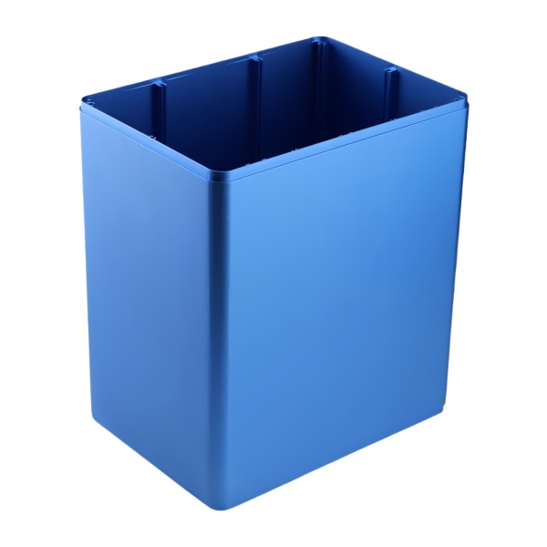
Open-top enclosure corner radius is the primary driver of both machining time and drop-test performance
A square open-top enclosure machined from aluminum block has four internal corners where the floor meets the walls. The radius specified for those corners—sharp (R0), small (R1–R3), or large (R5–R10)—determines the tooling strategy, the cycle time, and the part’s ability to survive a drop without cracking at the corner root.
Sharp internal corners require either a broaching operation (slow, tool-limited to simple straight profiles) or EDM (very slow, ~1 mm²/min) and create a stress concentration factor of 3.0 or higher at the exact corner point. A drop that impacts near a sharp corner almost always initiates a crack there because the impact stress is multiplied by Kt and exceeds the material’s fracture toughness. We strongly recommend R3 mm minimum for all internal corners of 6061-T6 enclosures intended for handheld or portable use; this radius can be achieved with a standard ballnose end mill in a single pass, adds no additional setup time, and reduces the corner Kt to about 1.8, which typically prevents crack initiation in drops from 1 meter onto concrete.
Wall thickness uniformity affects both the anodize appearance and the enclosure’s thermal behavior
When an open-top enclosure has non-uniform wall thickness—thicker on one side than another—the anodize process produces slightly different color tones because the current density varies with the local anode area (thicker sections carry more current per unit surface area and develop a slightly thicker oxide layer). For natural anodize this appears as a subtle shade variation; for colored anodize it can be a visibly different hue between the thick and thin walls. Additionally, non-uniform walls create hotspots under internal heat sources because the thin sections have lower thermal mass and conduct heat away more slowly.
We machine enclosure walls to within ±0.05 mm of the nominal thickness by using a roughing pass that leaves 0.3 mm stock, followed by a finishing pass that machines all walls in the same setup with the same tool at the same feed rate. This ensures that thermal expansion during machining affects all walls equally and that tool wear (which would cause gradual thickness change over a long production run) is detected and compensated before it creates out-of-tolerance parts. For enclosures with walls thinner than 1.5 mm where tool deflection becomes significant, we use a stub-length end mill (2× diameter protrusion maximum) and reduce the axial depth of cut to 0.5 mm per pass to maintain stiffness.
The base flatness determines whether the enclosure sits true or rocks when placed on a flat surface
The bottom face of an open-top enclosure is its primary datum surface—it defines how the enclosure sits on a mounting surface, how it aligns with adjacent assemblies, and whether the PCB or components inside are level relative to gravity. A flatness error of 0.05 mm over a 100 × 100 mm base means that one corner is 0.05 mm higher than the opposite corner; when the enclosure is bolted down at all four corners, the frame twists and the internal components experience bending stress that can crack solder joints or misalign connectors.
We machine the base as the last operation before the part leaves the machine, using a fresh insert and a light facing pass (0.15 mm DOC, 0.05 mm/rev feed) that minimizes cutting forces and thermal distortion. After machining, we verify flatness on a granite surface plate with a 0.01 mm dial indicator: the indicator is traversed across the base in a grid pattern (5 mm spacing in X and Y), and the total reading range (TIR) must not exceed 0.02 mm. Parts exceeding this limit receive a second light facing pass (0.05 mm stock removal) which corrects the error in most cases; persistent issues indicate fixture clamping distortion that requires adjusting the clamping force or adding support under the center of the base.
External corner radii and edge breaks determine the feel quality when handling the enclosure
The “feel” of an aluminum enclosure—how premium it feels when picked up, how comfortable it is to hold, and how professional it looks—is disproportionately influenced by the treatment of its external edges and corners. Sharp 90° external corners feel cheap and can snag on pockets, fabric, and cable jackets. Large radii (R5+) feel smooth but increase the effective outer dimensions and may interfere with adjacent parts in a tight assembly.
We apply a consistent R0.5–R1 mm break-edge to all external corners and edges unless the drawing specifies otherwise. This is done in the same setup as the final profiling operation using a chamfer mill or a deburring tool path that follows the entire perimeter. The result is an enclosure that feels like a finished product rather than a raw machined part. For consumer-facing enclosures where tactile quality is a selling point, we follow up the machined break-edge with a vibratory tumble (30 minutes in pyramid-shaped ceramic media with fine abrasive compound) that produces a uniformly rounded edge with a satin finish that feels smooth to the touch and catches light evenly.
Mounting hole position and perpendicularity affect whether the enclosure aligns correctly with its chassis
Open-top enclosures are typically mounted to a chassis or panel through holes in the base or through slots in the side walls. The positional tolerance of these holes relative to the enclosure’s internal features (PCB standoffs, connector cutouts, cable entry points) determines whether sub-assemblies fit without interference after the enclosure is mounted.
We establish a three-plane datum system for every enclosure: Datum A is the base (the mounted surface), Datum B is one side wall (the primary alignment feature), and Datum C is an adjacent side wall (the secondary alignment feature). All mounting holes are positioned relative to this datum frame with true position tolerances of 0.1 mm diameter at MMC for standard applications and 0.05 mm diameter at MMC for precision applications (optical instruments, medical devices). Perpendicularity of each mounting hole axis to Datum A is held to 0.03 mm TIR per 10 mm of hole depth to ensure that fasteners do not bind during assembly. These tolerances are verified on the CMM using best-fit circle measurements at the pitch diameter of threaded holes and at the minor diameter of clearance holes.
Anodize sealing quality is what prevents fingerprints and stains from permanently marking the enclosure
The final step in the anodize process—sealing—is what converts the porous oxide layer into a non-absorbent, corrosion-resistant surface. Poorly sealed anodize feels tacky to the touch, absorbs fingerprints and oils that cannot be wiped off, and provides inferior corrosion resistance because the pores remain open pathways for corrosive agents to reach the underlying aluminum.
We use a two-stage sealing process for all enclosure-grade anodize: first a hot water seal (98 °C deionized water, pH 5.5–6.0, 10 minutes) that hydrates the aluminum oxide to close the pores, then a nickel acetate cold seal (room temperature, 5 minutes) that deposits nickel hydroxide in any remaining pores for added corrosion resistance. Seal quality is verified per ASTM B680: a drop of acidified indigo solution is placed on the surface for 15 minutes, then rinsed off. If the surface stains (indicating unsealed pores), the batch is re-sealed. Our target is zero staining on 100 % of sampled parts (we test 3 parts per batch of up to 500). This specification has eliminated customer complaints about staining and fingerprint retention that we used to see roughly once per quarter before implementing the two-stage protocol.
This part belongs to our CNC Machining Parts range. The cnc machining parts pages collect the process notes, common materials and inspection points behind every product in the family.
Specifications
| Item | Anodized Aluminum CNC Machined Open-Top Square Enclosure |
|---|---|
| Brand | AUNOV |
| Designing | Send drawings, or send a sample to be measured, our engineers reply with a manufacturability assessment and pricing. |
| Tooling | Every die designed and built in our toolroom, held under your part number. |
| Samples | Samples for approval come with a dimensional report and material certification. |
| Materials | Aluminium leads the stock list for this part, alongside carbon steel (SPCC / DC01), 304 / 316 stainless steel, brass and copper, with grade selection confirmed at drawing review. |
| Surface finish | Plating, e-coat, powder coating, anodising or passivation, selected against the drawing requirement. |
| Processing | Staged deep drawing, with in-line annealing where the draw ratio requires, then pierced and CNC-machined in house. |
| Equipment | Our press floor runs 5-250 T mechanical and 250-500 T hydraulic presses, CNC turning centres and a climate-controlled CMM room. |
| Tolerance | Drawn tolerances held to +/-0.1 mm, +/-0.03 mm on machined surfaces. |
| Delivery terms | FOB is standard; DDP offered for EU and US, T/T and L/C; D/P on repeat accounts, call-off scheduling supported. |
Related Products


Request a Quote for This Part
Send a drawing or sketch — get material advice, tooling cost and a per-piece price within 24 hours (working days).