
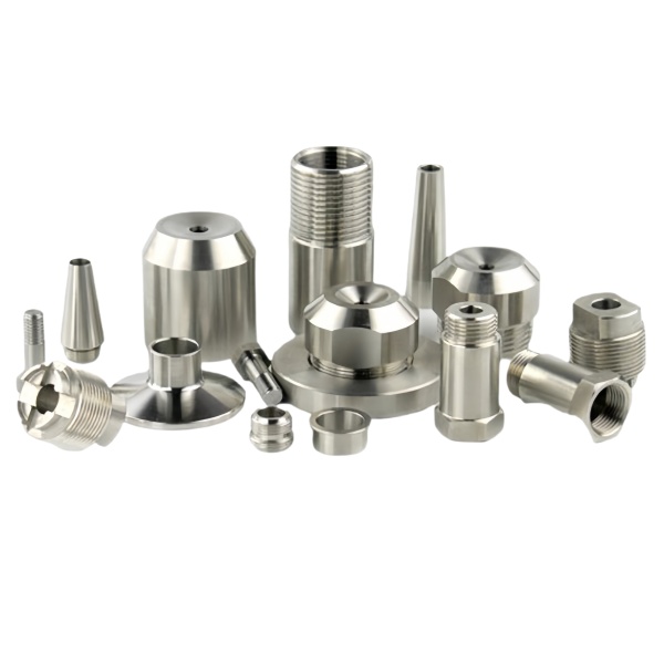
Dome cap wall-thickness distribution is controlled by the forming method, not by the drawing’s uniform spec
A machined dome cap—whether it serves as a pressure vessel end, a protective cover for a sensor, or an aesthetic enclosure—rarely has uniform wall thickness even when the drawing specifies a single nominal value. The reason is that the dome geometry forces material to stretch more at the apex than at the base during forming (whether by spinning, hydroforming, or deep drawing from plate). If the starting blank is a flat disc of uniform thickness, the formed dome will be thinnest at the pole (10–25 % thinner than the original) and thickest at the flange where the blank was clamped.
For CNC-machined domes cut from solid billet, we control wall thickness directly by programming the toolpath to maintain a constant normal offset from the outer surface. This produces a dome with wall thickness variation within ±0.05 mm of nominal—far better than any forming process can achieve. The trade-off is material utilization: a machined dome from solid 6061-T6 bar may use 3–5× the weight of a formed equivalent, which is why machining is only economical for diameters below 150 mm or for applications where the material removal cost is justified by the dimensional accuracy and the absence of forming-induced residual stress.
Residual stress from machining can cause a machined dome to warp after it leaves the fixture
When a dome shape is machined from a solid block or bar, the removal of material releases residual stresses that were present in the raw stock (from rolling, heat treatment, or prior forming operations). If those stresses are not symmetrically distributed around the dome axis, the part will warp when unclamped—sometimes visibly, sometimes by amounts that are only detected during assembly when the dome does not seat flat against its mating flange.
The magnitude of warping depends on the stock condition, the depth of cut, and the symmetry of the machining sequence. For 6061-T6 extruded round bar (the most common stock for machined domes), the residual stress pattern is typically axisymmetric but varies with distance from the bar center: the core is in compression while the surface is in tension. Machining a dome from the center of the bar outward in a spiral toolpath tends to release stress gradually and produces minimal warping (typically under 0.02 mm TIR on a 100 mm diameter dome). Machining from one side to the other in parallel passes can release stress asymmetrically and produce warping of 0.1–0.3 mm on the same part. We always use the concentric spiral approach for domes and add a stress-relieve cycle (heating to 400 °C for 2 hours, slow cool) if the dome has a flat sealing face that must be within 0.05 mm flatness.
The tangent line between the dome radius and the flange is a stress concentrator under internal pressure
For dome caps that function as pressure-retaining components (sensor housings, small accumulator ends, vacuum chamber ports), the junction between the spherical dome and the flat flange is the location of maximum bending stress under internal pressure. Shell theory predicts that the discontinuity in curvature at this junction generates a localized bending moment that decays exponentially with distance from the junction—but the peak value can be 2–4× the membrane stress in the dome itself.
We address this in one of three ways depending on the pressure rating:
- Below 0.5 MPa: Add a tangential blend radius (R5–R10 mm depending on dome diameter) between the dome and the flange. This smooths the curvature transition and reduces the bending stress concentration factor from about 2.5 to about 1.3. The radius is machined with a ballnose tool as part of the dome profiling operation.
- 0.5–5 MPa: Increase the wall thickness at the junction by 30–50 % (a “thickened knuckle”) and maintain the blend radius. The added material carries the bending moment without yielding.
- Above 5 MPa: Redesign the part with a torispherical head profile (a specific combination of crown radius, knuckle radius, and cylinder length) that follows ASME BPVC Section VIII rules for formed heads. Even though this part is machined rather than formed, following the same profile proportions ensures that the stress distribution matches the code-predicted values and simplifies any future pressure-vessel certification.
Machining a sharp cone tip requires a decreasing step-over as the diameter approaches zero
Some dome caps integrate a conical tip—a probe housing, a nozzle body, or an aerodynamic fairing. Machining a cone to a sharp point (or to a truncated tip with a small flat) presents a toolpath challenge: as the diameter decreases toward the tip, the scallop height left by each pass of a ballnose mill becomes a larger fraction of the local radius, producing a visibly faceted surface unless the step-over is reduced proportionally.
We program cone machining with adaptive step-over: starting at 0.3 mm step-over at the base (where the cone diameter is large and the scallop height is negligible), reducing linearly to 0.05 mm step-over within 5 mm of the tip. This keeps the theoretical scallop height below 2 µm across the entire cone surface, which polishes to a mirror finish (Ra < 0.2 µm) with minimal hand work. The trade-off is longer machining time near the tip—the final 5 mm of a 30° cone may take as long as the rest of the cone combined—but the alternative (machining at uniform step-over and then hand-finishing the tip) is slower overall and less repeatable.
Surface finish on the external dome affects both appearance and cleanability in sanitary applications
For dome caps used in food-processing, pharmaceutical, or laboratory equipment, the external surface finish is not just cosmetic—it determines how easily the part can be cleaned and sterilized. A surface with Ra above 0.8 µm has microscopic valleys that can harbor bacteria and biofilm that survive standard CIP (clean-in-place) protocols. A surface polished to Ra 0.4 µm or better reduces bacterial adhesion by roughly 80 % compared to a standard machined finish, according to studies published in the Journal of Food Engineering.
We offer three finish levels for sanitary domes:
- Standard machined: Ra 1.6 µm, suitable for non-contact applications where the dome is not exposed to product flow. Achieved with a fresh carbide insert at recommended feeds and speeds.
- Sanitary polish: Ra 0.4 µm, achieved by machining followed by progressive abrasive polishing (320 → 600 → 800 grit) and a final buff with a cotton wheel and fine compound. Adds approximately 3–5 minutes per part depending on dome size.
- Electropolish: Ra 0.2 µm or better, achieved by immersing the machined part in an electrolytic bath that removes 0.025–0.05 mm of surface material. Electropolishing not only smooths the surface but also removes embedded contaminants and the work-hardened layer from machining, which further improves corrosion resistance. Required for USP Class VI and FDA-compliant applications.
How we verify that a dome cap meets its pressure or vacuum rating before shipment
Every dome cap designated as pressure-retaining on the customer drawing undergoes a proof test before shipping. The test pressure is 1.5× the design pressure (per ASME BPVC practice) held for 10 minutes with no visible permanent deformation. After the test, we re-measure critical dimensions (flange flatness, bore diameter, overall height) and compare to pre-test values; any change greater than 0.02 mm triggers a material review and possible scrap decision.
For vacuum-rated domes (common in sensor housings and laboratory chambers), the test is a vacuum hold at the specified rating (often 0.1 MPa absolute, i.e., full vacuum) for 30 minutes with a leak rate measurement using a helium mass spectrometer. The acceptance criterion is a leak rate below 1×10⁻⁸ atm·cc/s—tight enough that the dome will not lose vacuum over a typical service interval of 6–12 months without repumping. Parts that fail the leak test are inspected for porosity (casting) or micro-cracks (machining/handling); if no defect is found, the flange sealing surface is re-lapped and the part is re-tested.
Our CNC Machining Parts range is where this part sits. The cnc machining parts pages carry the process notes, common materials and inspection points behind every product in the family.
Specifications
| Item | Stainless Steel CNC Machined Dome Caps and Cones |
|---|---|
| Brand | AUNOV |
| Designing | A drawing file or a physical sample starts the review, our engineers reply with a manufacturability assessment and pricing. |
| Tooling | Dies engineered and produced in our own toolroom, with your part number on the tool record. |
| Samples | Sample parts arrive with a dimensional report plus material certs. |
| Materials | Stock for this part leads with 304 / 316 stainless steel, alongside carbon steel (SPCC / DC01), aluminium, brass and copper, and the grade is fixed at the drawing review. |
| Surface finish | Surface treatment per the drawing: plating, e-coat, powder coating, anodising, passivation, selected against the drawing requirement. |
| Processing | Staged deep drawing with in-line annealing where needed, then pierced and CNC-machined in house. |
| Equipment | Mechanical presses 5-250 T and hydraulic presses 250-500 T, in-house CNC cells and a temperature-controlled inspection room. |
| Tolerance | +/-0.1 mm as-drawn, with machined features to +/-0.03 mm. |
| Delivery terms | Standard terms FOB, DDP offered to EU and US, T/T or L/C, with D/P for repeat business, call-off schedules and blanket orders supported. |
Related Products


Request a Quote for This Part
Send a drawing or sketch — get material advice, tooling cost and a per-piece price within 24 hours (working days).