
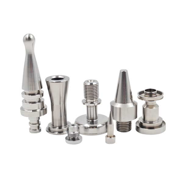
Nozzle exit geometry determines the spray pattern more than the upstream pressure does
On a machined nozzle—whether it is a fuel injector tip, a cooling spray nozzle, or an atomizer for coating applications—the shape of the final 0.5 mm of the exit orifice has more influence on the spray cone angle and droplet size distribution than any change in supply pressure below the turbulent transition. A sharp-edged orifice with a 90° inlet corner produces a vena contracta that reduces the effective flow area by roughly 40 % compared to the geometric area, while also generating a coherent jet that breaks up farther downstream (larger droplets). A rounded inlet with a radius equal to half the orifice diameter eliminates the vena contracta, increases the discharge coefficient from about 0.61 to 0.9–0.95, and promotes earlier breakup into smaller droplets at the same pressure.
We machine the inlet profile using a ballnose end mill whose radius matches the design intent, then polish the surface to Ra 0.4 µm or better to avoid turbulence-inducing scratches that distort the spray pattern. The difference between a as-machined finish (Ra 1.6 µm) and a polished finish (Ra 0.4 µm) on a 0.8 mm fuel orifice is measurable in a spray test rig: the polished orifice produces a spray cone angle within ±2° of nominal, while the as-machined one varies by ±8–10° because microscopic ridges act as unintentional flow vanes that bias the liquid to one side.
Conical fitting taper angle tolerance controls both the seal integrity and the assembly force
A conical fitting—a tapered thread (NPT/BSP), a JIC 37° flare seat, or a custom-tapered interference joint—relies on angle matching between the male and female tapers for its seal. The axial position at which contact occurs is determined by the combined angle error: if the male taper is 0.5° shallower than spec and the female taper is 0.3° steeper, the effective angle mismatch is 0.8°, and the contact ring shifts axially by an amount proportional to that error times the length of engagement.
On a standard 37° JIC seat machined into 316 stainless steel, we hold the included angle to 37° ±0.25° and verify it with a conical ring gauge that is blued and inserted into the seat; the contact pattern must show a continuous band occupying at least 70 % of the seat width, centered on the mid-radius. A seat that contacts only at the inner edge (indicating the angle is too steep) will leak under impulse loads because the contact stress exceeds the yield strength of the softer material (often aluminum on the mating fitting) and extrudes the material outward, opening a gap. A seat contacting only at the outer edge (angle too shallow) will initially seal but will loosen under vibration as the contact ring works outward.
Internal surface finish in the bore affects flow rate consistency across a production batch
For nozzles with a through-bore that acts as a flow restrictor—the case in many hydraulic control nozzles and metering orifices—the flow rate is proportional to the fourth power of the bore diameter (per the Hagen-Poiseuille equation for laminar flow) but also sensitive to surface roughness when the Reynolds number falls below 2300. In that regime, the friction factor is a function of relative roughness (ε/D), and a bore finished at Ra 3.2 µm can deliver 5–8 % less flow than an identical bore at Ra 0.8 µm, even though both measure the same diameter with a plug gauge.
This batch-to-batch variation is a chronic problem for customers who calibrate their systems against a master nozzle and then find that replacement nozzles from a new batch require re-calibration. We address it by specifying a maximum Ra of 1.6 µm for all flow-critical bores above 2 mm diameter, and 0.8 µm for bores below 2 mm where the relative roughness effect is amplified. The finishing operation is a pull-through honing pass that simultaneously sizes the bore and establishes the surface texture in one stroke, adding about 20 seconds per part compared to as-drilled.
Material selection between 303, 304, and 316 stainless steel changes machinability more than corrosion resistance
Most stainless steel nozzles and fittings are specified as “304 or equivalent” on customer drawings, which gives us latitude in material selection. The practical choice among common austenitic grades is driven primarily by machinability, not by corrosion resistance, because the majority of these parts operate in non-aggressive environments (hydraulic oil, compressed air, water-glycol mixtures).
303 stainless steel (UNS S30300) contains sulfur additions (0.15 % min) that make it machine 30–40 % faster than 304 with longer tool life and better surface finish. The trade-off is reduced corrosion resistance in chloride environments and reduced weldability—neither of which matters for a machined nozzle that will not be welded. For parts with bores below 1 mm where tool deflection and chip evacuation are the limiting factors, 303 can be the difference between a stable machining process and one that produces 10 % scrap due to tool breakage. We default to 304 only when the drawing explicitly calls it out or when the service environment includes seawater or deicing salts; otherwise we use 303 and note the substitution on the material certificate.
Heat-affected zone from secondary operations can alter the nozzle’s flow characteristics
Some nozzle designs require a secondary operation after the initial machining: laser drilling of a micro-orifice, TIG welding of a baffle or filter screen, or induction hardening of the seat surface. Each of these introduces localized heat that can alter the material microstructure and dimensions in the heat-affected zone (HAZ). On a nozzle with a 0.3 mm laser-drilled orifice located 2 mm from a TIG weld, the HAZ from the weld can cause enough thermal distortion to shift the orifice position by 0.01–0.02 mm and locally anneal the work-hardened layer around the orifice, changing its edge condition from cut to recast.
We sequence operations so that any thermal process (welding, brazing, induction heating) is completed before the final precision machining of flow-critical features. If welding must come after (as when a filter screen is tack-welded into place), we use a low-heat-input process such as laser welding or micro-TIG with pulse parameters tuned to keep the HAZ width below 0.5 mm. Post-weld, we re-measure the orifice diameter and flow rate and adjust with a controlled micro-honing pass if the drift exceeds 2 % of nominal.
How we certify that a nozzle batch meets the customer’s flow specification before shipping
Every batch of flow-critical nozzles receives a 100 % flow test using a calibrated air or liquid bench, depending on the customer’s specified test medium. The test measures actual flow rate at the nominal pressure drop and compares it to the drawing’s minimum and maximum limits. Parts outside the limits are segregated: those below minimum are inspected for burrs or foreign material and re-tested; those above maximum (usually indicating an oversize bore or damaged orifice edge) are scrapped.
In addition to the go/no-go flow check, we pull a statistical sample (n=5 for batches under 100, n=10 for larger batches) and perform a detailed characterization: flow vs. pressure curve (5 points), spray pattern photography (for atomizing nozzles), and dimensional CMM report on the orifice geometry. This data is packaged with each shipment in a Certificate of Conformance that includes the raw test values, not just a pass/fail stamp. Several OEM customers have told us that this level of traceability was a deciding factor in awarding repeat business, because it allows them to skip incoming inspection and dock-to-stock the parts directly.
This part belongs to our CNC Machining Parts range. The cnc machining parts pages collect the process notes, common materials and inspection points behind every product in the family.
Specifications
| Item | Stainless Steel CNC Machined Nozzles and Conical Fittings |
|---|---|
| Brand | AUNOV |
| Designing | Send the drawing, or a fitting sample we can measure, a manufacturability review comes back with the quotation. |
| Tooling | Tooling designed and cut in house, with your part number on the tool record. |
| Samples | The first-article set ships with dimensional data and material certification. |
| Materials | Stock for this part leads with 304 / 316 stainless steel, alongside carbon steel (SPCC / DC01), aluminium, brass and copper, and the grade is fixed at the drawing review. |
| Surface finish | Finishes on offer: plating, e-coat, powder coating, anodising or passivation, set by your print. |
| Processing | Multi-stage drawing, annealed in line where wall thinning calls for it, with piercing and finish machining under the same roof. |
| Equipment | Mechanical presses 5-250 T and hydraulic presses 250-500 T, CNC turning centres, plus a climate-controlled CMM room. |
| Tolerance | As-drawn tolerance +/-0.1 mm, machined features held to +/-0.03 mm. |
| Delivery terms | FOB standard, DDP offered for EU and US, T/T and L/C; D/P on repeat accounts, call-off schedules supported. |
Related Products


Frequently Asked Questions
Why does the exit geometry set the spray pattern more than pressure?
On a machined nozzle, the shape of the final 0.5 mm of the exit orifice has more influence on the spray cone angle and droplet size than any change in supply pressure below the turbulent transition. A sharp-edged orifice with a 90 degree inlet corner produces a vena contracta that reduces the effective flow area by roughly forty percent. A rounded inlet with a radius equal to half the orifice diameter eliminates it and raises the discharge coefficient from about 0.61 to 0.9-0.95.
Why does the conical fitting’s taper angle control both seal and assembly force?
A conical fitting, whether a tapered thread, a JIC 37 degree flare seat, or a custom-tapered interference joint, relies on angle matching between the male and female tapers for its seal. The axial position at which contact occurs is set by the combined angle error, so a mismatch shifts the contact ring axially. On a standard 37 degree JIC seat machined into 316 stainless steel we hold the included angle to 37 degrees plus or minus 0.25 degree and verify it with a blued conical ring gauge.
Why does internal surface finish change flow rate across a batch?
In the rough-flow regime the friction factor is a function of relative roughness, and a bore finished at Ra 3.2 micrometres can deliver five to eight percent less flow than an identical bore at Ra 0.8 micrometres, even though both measure the same diameter with a plug gauge. We specify a maximum Ra of 1.6 micrometres for flow-critical bores above 2 mm and 0.8 for bores below 2 mm. A pull-through honing pass sizes the bore and sets the texture in one stroke.
Why does 303 versus 304 versus 316 change machinability more than corrosion?
Most stainless steel nozzles are specified as 304 or equivalent, which gives latitude in material selection. 303 stainless steel contains sulfur additions that make it machine thirty to forty percent faster than 304 with longer tool life and better surface finish, at the cost of reduced corrosion resistance in chloride environments and reduced weldability. Neither trade-off matters for a machined nozzle that will not be welded, and for bores below 1 mm the 303 choice can be the difference between a stable process and scrap from tool breakage.
Request a Quote for This Part
Send a drawing or sketch — get material advice, tooling cost and a per-piece price within 24 hours (working days).