
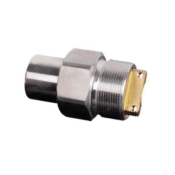
Connector body thread durability determines whether the sensor survives repeated field re-connections
A sensor connector body—the threaded housing that mates the sensor to its cable connector—will be threaded and unthreaded many times over its service life: during installation, during troubleshooting, during sensor replacement. Each cycle wears the thread flanks. In stainless steel-on-stainless steel pairs (the most common combination for industrial sensors), the wear mechanism is galling: asperities cold-weld and shear, removing material and eventually destroying the thread’s fit.
We extend thread life with three measures: a thread fit class of 2A/2B rather than 3A/3B (the extra clearance of the looser class gives wear debris somewhere to go and reduces metal-to-metal contact pressure); a surface treatment on one member of the pair (electroless nickel on the connector body, or a dry-film lubricant per MIL-PRF-46010 on either part) that prevents cold-welding; and a lead-in chamfer of 1.5 thread pitches on the first thread, which prevents cross-threading damage that would otherwise doom the connection from the first careless assembly.
Sealing at the connector interface: O-ring under the thread vs. radial seal on the mating plug
The connector body must seal the sensor’s internal electronics from the environment at two interfaces: the front (process side, sealed by the sensor’s own sheath or a separate gland) and the rear (cable side, sealed at the connector mating face). The rear seal has two standard architectures:
- Axial face seal: An O-ring in a dovetail or rectangular groove on the connector’s mating face compresses axially when the mating connector is torqued down. Simple to machine (one groove), insensitive to radial runout, and the seal is visible for inspection. Torque-sensitive: under-torquing under-compresses the O-ring; over-torquing extrudes it.
- Radial seal: The mating connector’s cylindrical plug enters the connector body’s bore, and an O-ring on the plug seals radially against the body’s bore surface. More forgiving of axial tolerance stack (the plug can seat at varying depths with the seal still working), but demands a smooth, round bore (Ra ≤ 0.8 µm, ovality ≤ 0.02 mm) over the full seal travel—more machining effort on the body.
We machine the radial-seal bore with a fine boring pass and gauge it with a ball micrometer at three depths; the axial-seal groove is verified with a groove micrometer and a radius gauge at the groove corners (the corners must be free of burrs—an O-ring dragged over a burred groove edge is cut before it ever compresses).
Solder pot or wire channel geometry in the connector body affects the probe’s vibration life
Inside the connector body, the sensor’s signal wires either terminate at solder pots (cup-shaped terminals filled with solder) or run through wire channels to screw terminals or a flying lead. The geometry of these internal features determines how the wires respond to vibration.
A wire that exits a solder pot at a stiff right angle will work-harden at the bend and break after 10⁵–10⁶ vibration cycles. A wire that exits through a radiused, strain-relieved channel (R ≥ 2 mm at the exit, plus a compliant grommet or a bead of RTV silicone where the wire exits the body) survives 10⁷+ cycles. We machine wire exit channels with a ballnose end mill to produce a minimum R2 exit radius, and we specify the strain-relief grommet on the assembly drawing even when the customer’s drawing is silent—a broken lead wire inside the connector is the most common cause of intermittent sensor faults and the cheapest to prevent.
Material choice for the connector body: 303 vs. 316 vs. nickel-plated brass
The connector body sits at the cable end of the sensor—usually outside the harshest environment but still exposed to washdown, condensation, and handling:
- 303 stainless steel: The machining favorite for connector bodies (sulfur additions give fast, clean machining of the small, complex internal features). Corrosion resistance adequate for general industrial environments. Our default unless the connector faces chloride exposure.
- 316 stainless steel: Required for marine, food-processing (salt washdown), and outdoor installations. Machines slower (~25 % longer cycle time on small features) and work-hardens under forming tools, but the molybdenum content prevents the pitting that eventually creeps under 303 connector threads in chloride environments.
- Nickel-plated brass: The traditional connector material (think classic M12 connector hardware). Excellent thread wear (brass does not gall against the stainless steel mating nut) and RF shielding (when the plating is continuous). Limited to ~100 °C service and non-corrosive environments (the plating protects the brass, but any scratch exposes it). Cost sits between 303 and 316.
How we verify sensor connector bodies before shipping
Final inspection:
- Threads: Go/no-go gauges per specified class on 100 % of parts. Lead-in chamfer verified visually (no burled first thread).
- Seal interfaces: O-ring grooves: groove diameter, width, and corner condition (radius gauge + 10× visual). Radial seal bores: ball micrometer at three depths; roundness and surface finish on first article.
- Internal features: Solder pot diameter and depth (go/no-go pin + depth gauge); wire channel exit radius verified on first article by sectioning one part per design.
- Mating trial: One part per batch mated with the customer’s connector (or a master). Verification: threads engage smoothly to full depth without galling, seal compresses (verified by pressure hold if the connector is pressure-rated), and the mating connector releases without excessive torque.
- Environmental sealing (if IP-rated): One assembly per batch tested to its IP rating (IP65: water jet; IP67: 1 m immersion for 30 minutes) with moisture-indicating paper inside. Acceptance: no moisture ingress.
CNC Machining Parts is the parent range for parts like this one; the overview page gathers the tooling logic, finishing options and tolerance notes that apply across the family.
Specifications
| Item | Stainless Steel CNC Machined Sensor Connector Body |
|---|---|
| Brand | AUNOV |
| Designing | Send us your 2D drawing, or mail a body sample for measurement, you get a DFM review together with the quotation. |
| Tooling | Every die designed and built in our toolroom, with your part number on the tool record. |
| Samples | The first-article set ships with a dimensional report and material certificate. |
| Materials | Stock for this part leads with 304 / 316 stainless steel, alongside carbon steel (SPCC / DC01), aluminium, brass and copper, with grade selection confirmed at drawing review. |
| Surface finish | Zinc, nickel or chrome plating, e-coat, powder coat, anodising or passivation, per the drawing. |
| Processing | Multi-stage drawing, annealed in line where wall thinning calls for it, pierced and machined on the same floor. |
| Equipment | Press capacity from 5 to 500 T across mechanical and hydraulic lines, CNC turning centres and a climate-controlled CMM room. |
| Tolerance | As-drawn work holds +/-0.1 mm; machined surfaces hold +/-0.03 mm. |
| Delivery terms | Prices FOB, with DDP for EU and US on request, T/T or L/C, with D/P for repeat business, call-off schedules and blanket orders supported. |
Related Products



Request a Quote for This Part
Send a drawing or sketch — get material advice, tooling cost and a per-piece price within 24 hours (working days).