
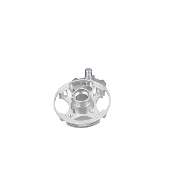
The bores decide the valve, and the outside is just where the bolts go
In a precision valve body housing, the features that determine whether the finished assembly works are almost all internal. The external form — the mounting pads, the bolt holes, the flange outline — is what the machine tool can see and what the machinist can measure in the setup, and it consequently receives most of the attention in a machine shop. The internal spools, seats, passages and clearances are what the fluid sees, and they are where the performance actually lives.
AUNOV machines precision aluminium valve body housings to ±0.03 mm on machined features, from 6061 and similar alloys, with finishing by anodizing, plating or coating per the drawing. The housings in this class carry spool or plunger bores, seat features, cross-drilled passage networks, and one or more sealing interfaces. This page works through the internal geometry decisions in the order they affect the finished valve.
Spool bore diameter, roundness and straightness
A spool bore is not a hole, it is a hydrodynamic environment. The spool and the bore form a clearance pair, and the fluid film inside that clearance does three things at once: it lubricates, it hydraulically centres the spool to a degree, and it leaks. All three depend on the bore being round, straight and consistently sized along its length.
The diameter specification is the easy part. The hard part is the geometry that accompanies it:
- Roundness. A bore that is trefoil by three micrometres will have three tight spots around the spool. Leakage varies around the circumference and the spool is pushed off centre toward one side, which raises local friction and produces uneven wear. A roundness specification of half the clearance, or a maximum of two to three micrometres on a typical spool valve, is realistic and should be written down.
- Cylindricity and straightness over the spool land travel. What matters is not the average bore diameter but the variation over the region the spool traverses. A bore that tapers by five micrometres over the travel length will make the spool easier to move at one end than the other. For a proportional valve this shows up as a gain that changes with position, which is a control problem and not a machining curiosity.
- Surface finish and the direction of the marks. A fine circumferential finish helps the spool form a film. A residual helical feed mark from a boring operation acts as a pumping groove and can drive fluid along the bore, which shows up as an internal leak that changes with spool rotation. Where a valve is flow-sensitive, the bore finish is best produced by a single continuous pass or by honing, which leaves the cross-hatch pattern that is known to hold lubricant well.
- Edge quality at the land crossings. The transition where the spool land uncovers a port is where the valve’s metering characteristic is set. A burr or a rounded edge at that crossing changes the flow area at a given spool position, which changes the valve’s response. These edges should be broken to a controlled radius, not left as cut and not heavily deburred into roundness. This is a case where the specification must call out both the maximum and, unusually, a limit on how much material may be removed.
Ports, passages and the interference rules
The passage network inside a valve body is a set of drilled or milled cavities that intersect each other and the spool bore. Each intersection needs to be planned rather than discovered, because the geometry at the intersection determines the flow characteristic and, in a pressure-bearing body, the local stress.
| Intersection type | What goes wrong | Design response |
|---|---|---|
| Cross-drill meets spool bore | Sharp drilled corner becomes a burr trap and a stress raiser; the bore edge shape sets the metering curve | Relieve the junction, break the bore edge to a controlled radius, specify deburring and verify by borescope |
| Two cross-drills intersect | Drill walk and breakout burr; the intersection may be smaller than either drill and restricts flow | Model the intersection as the flow area, not the drill diameter; allow a spot-face or a larger passage at the junction |
| Passage meets a wall at an angle | Thin ligament on one side; a sharp-angle intersection may be too thin to seal | Maintain a minimum wall on the acute side, or relocate the passage; thin ligaments between passages are the most common cause of a leaking body |
| Plugged end of a drilled passage | The plug is a permanent leak path and is often overlooked in the leak test plan | Specify the plug type (pressed ball, threaded plug, welded), its seating method, and include it in the pressure test |
| Blind passage | Traps chips and fluid; releases contamination into the valve over time | Break through where possible, otherwise specify a radiused floor plus a documented cleaning verification |
The ligament point deserves emphasis. The distance between two adjacent passages, or between a passage and the outside of the body, is the real pressure boundary in a machined aluminium valve body. That distance is rarely dimensioned on the drawing because it is a by-product of two other dimensions, and it is usually checked by nobody. Where a body carries two passages at different pressures in close proximity, the intervening wall should be called out as a controlled dimension, and its thickness should be set from the pressure rating rather than from the space left over.
Sealing interfaces in aluminium
Aluminium bodies seal in three ways in this product class, and each one places a different demand on the machining.
- O-ring in a machined groove. The groove’s width and depth come from the O-ring’s cross-section and the target squeeze, which is typically between 15 and 25 percent for a static seal. On aluminium, thermal growth must be considered because the body and the mating part may be different materials. The groove floor finish should be smooth enough not to abrade the elastomer, and the groove side walls should be free of burrs, since a burr on the side wall will cut the O-ring during assembly. The most frequently missed dimension is the groove’s inside diameter, which sets how far the O-ring stretches.
- Gasketed flat face. The controlling features are flatness across the seal track and the absence of scratches that cross it. A machined face at 1.6 micrometre Ra with a clean, non-directional finish will seal against a soft gasket; the same face with a radial score will not. Where a face is large, flatness is more important than roughness, and it should be measured on a surface plate or a flatness gauge, not inferred from the surface finish.
- Metal-to-metal cone or face seal on a port. The seal is created by elastic interference, which means the assembly torque is a functional parameter of the joint. On aluminium, a steel fitting tightened into an aluminium seat at high torque will deform the seat over repeated assemblies. That is why a torque figure belongs on the assembly drawing and why the mating component’s material should be considered when the body material is chosen.
Machining sequence and the datum problem
The internal features of a valve body cannot all be produced from the same setup. The spool bore comes from one direction, a good deal of the passage network from another, and the mounting and sealing faces from a third or fourth. Every additional setup introduces a datum transfer, and every datum transfer adds its contribution to the positional error between features.
There is a straightforward principle worth defending at the drawing stage: features that must be accurately positioned relative to each other should be machined in the same setup. If the drawing requires that the spool bore and the port face be concentric or perpendicular to a tight tolerance, the manufacturability review will look for a way to produce them without an intervening re-clamp. The most common way is to leave a machining boss or an un-machined ring that can be gripped for the second operation and then removed. This is often worth adding as a temporary casting or billet feature even though it must be machined away on the finished part.
Where a re-clamp is unavoidable, the datum should be an actual functional surface rather than a provisional one. Fixturing to a rough casting surface and then machining a bore relative to it produces a body whose bore is accurate relative to a surface nobody uses. Machining a preliminary face, then using the machined face as the datum for everything else, produces the chain that the drawing intends.
Cleanliness, and why a valve body is a different problem from a bracket
A machined bracket can be cleaned at the end and shipped. A valve body carries its own contamination into the assembly and injects it into the working clearances of the valve. That makes cleanliness a design attribute rather than a shop habit.
- Chips hide in intersections. The junction between a cross-drill and the bore is where a chip will lodge, and a single chip in a spool bore can score the bore on the first stroke of the valve. Deburring must be specified as a controlled operation with a defined method for each cavity, and the result should be verified by borescope inspection on a sample basis. Where the geometry makes a cavity inaccessible, that is a design defect to be corrected, not an inspection problem to be worked around.
- Masking for the finish interacts with cleaning. Anodizing or coating a body with a complex interior may leave masking material residue, and the masking itself has to be removed after the process rather than blended in. The masking list and the cleaning sequence need to be planned together.
- The shipping protection matters because the interior is unreachable. A body with an open port and an open cavity will collect dust through the port, and no receiving inspection can see inside it. Plug the ports with purpose-made caps or plugs, and specify that they remain in place until assembly.
Pressure, fatigue and thermal cycling
Aluminium has no fatigue endurance limit, so a valve body in cyclic pressure service must be evaluated against a finite life. The places to look are the ones a static analysis does not flag: the fillet at the base of a boss, the acute-angle ligament between two passages, the counterbore edge at the bottom of a threaded port, and the corner where a cross-drill breaks into the main bore. Those are the four locations where cyclic aluminium parts in this family tend to crack.
Thermal cycling adds a second mechanism. If the body is aluminium and a mating component is steel or brass, the differential expansion at each temperature cycle works the joint, and a bolted flange will relax its preload over time. Two countermeasures apply: use a gasket with defined compression and recovery rather than relying on metal-to-metal contact, and specify bolt torque with a defined re-torque interval, or use belleville washers to maintain preload across the differential expansion.
Inspection plan for a precision valve body
- Spool bore diameter at three positions along its length, to detect taper, plus roundness on a roundness tester.
- Cylindricity or straightness over the spool travel region, referenced to the bore axis.
- Port face perpendicularity and position relative to the bore axis, on the CMM.
- Position of every mounting hole and port relative to the same datum.
- Wall thickness or ligament dimensions at each location identified as pressure-critical, by ultrasonic measurement or by sectioning a sample.
- Seat angle and seal-track flatness, with the measurement method stated.
- Burr condition and cleanliness of every internal intersection, by borescope on a sampled basis.
- Leak test at the rated pressure with the acceptance criterion given as a mass-flow leak rate.
Honing improves roundness, but the pre-hone bore has to allow for it
Can the spool bore be honed after machining?
Yes, and for a flow-sensitive or proportional valve it is often the right choice because honing produces the cross-hatch that holds a lubricating film and it improves roundness. It adds an operation and it removes material, so the pre-hone bore must be sized accordingly, and masking for any subsequent finish has to keep the honed surface clean.
How much wall is enough between two passages?
It depends on the pressure and on the temperature, but the governing factor in service is usually fatigue rather than static burst. A reasonable starting point for an aluminium body in a moderate-pressure hydraulic application is a ligament equal to at least the nominal wall thickness used elsewhere in the body, and never less than 2 mm. Where the ligament is smaller, it should be justified explicitly rather than left as a by-product.
Does anodizing the interior cause problems?
It can, in two ways: it changes the spool bore dimensions, and a hard oxide is abrasive to a sliding spool. Most precision valve bodies mask the spool bore and anodize only the exterior, and we will flag this during the drawing review.
Can a valve body be made from a casting rather than billet?
Yes, and for a body with a complex passage network a casting is often the only economical route. The trade is that a casting’s wall sections vary and porosity can appear in a critical ligament, so a cast body usually carries a higher inspection burden and, for a pressure-critical application, may need to be pressure tested at a higher rate. Tell us the anticipated volume and we will quote both routes.
This part belongs to our CNC Machining Parts range. The cnc machining parts pages collect the process notes, common materials and inspection points behind every product in the family.
Specifications
| Item | Precision CNC Machined Aluminum Valve Body Housing |
|---|---|
| Brand | AUNOV |
| Designing | A drawing file or a physical sample starts the review, our engineers reply with a manufacturability assessment and pricing. |
| Tooling | Tooling designed and cut in house, held and maintained under your part number. |
| Samples | Approval samples ship with a full dimensional report and material certification. |
| Materials | Stock for this part leads with aluminium, alongside carbon steel (SPCC / DC01), 304 / 316 stainless steel, brass and copper, per the drawing. |
| Surface finish | Finish options: plating, e-coat, powder coating, anodising or passivation, per the drawing. |
| Processing | Staged deep drawing, with in-line annealing where the draw ratio requires, with piercing and finish machining under the same roof. |
| Equipment | Mechanical presses 5-250 T, hydraulic presses 250-500 T, in-house CNC cells and a temperature-controlled inspection room. |
| Tolerance | Drawn tolerances held to +/-0.1 mm, with machined features to +/-0.03 mm. |
| Delivery terms | FOB standard, DDP offered for EU and US, T/T or L/C, with D/P for repeat business, call-off schedules supported. |
Related Products


Request a Quote for This Part
Send a drawing or sketch — get material advice, tooling cost and a per-piece price within 24 hours (working days).