
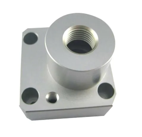
A hex cap nut is a part most people think of as a commodity, and it is worth being clear about the small number of things that make it a precision component rather than a commodity. A cap nut is doing four jobs at once: it has to carry the clamp load without stripping its own thread, it has to spread that load over a large bearing area, it has to resist being loosened by vibration, and it has to do both of those in whatever environment it happens to be in. A machined stainless steel cap nut that is used as a high-strength fastener has three separate functional dimensions – the thread, the bearing face, and the height – and each of them has its own failure mode.
The reason to machine it rather than buy a standard fastener is usually one of three: a height that does not exist as a standard, a material that a standard fastener does not offer in the size required, or a dimensional control that a standard nut does not carry. Which of those three it is determines almost everything else about the part.
Thread height, which is the dimension that makes it a machined nut
A standard hex nut has a thickness defined as a fraction of its width across flats, and on a small nut that gives a very short thread. A machined cap nut is typically taller than the standard proportion, and that extra height is the whole reason for the part.
More thread height is worth more than the number of millimetres suggests. Thread shear capacity scales with the thread’s engagement length and with its minor diameter, so going from a thin nut to a tall nut converts a small increase in steel into a meaningful increase in strength. This is the standard approach when a joint has to be strong and the standard nut size has to be kept for the wrench.
Three things this makes functional:
- The thread’s pitch diameter, which is what the fastener mates to and what carries the load. It has to be at the fastener’s class, and on a machined nut this is set by the turning operation and is very repeatable.
- The thread’s runout and chamfer, which on a tall nut have to be a controlled feature rather than an accident. A chamfer that is too aggressive removes thread at the entry, and a thread that is not fully formed at the face will start its load path on the second thread rather than the first – which is a modest loss and is easy to miss.
- The height’s tolerance. A nut’s height matters functionally because it sets how far the fastener protrudes and therefore whether the joint has room. On a tall nut this is a real, coordinated dimension with the fastener and the clamped stack, and it should be stated rather than assumed.
The bearing face, which is where the load actually goes
Between the nut and the joint there are two surfaces: the nut’s own bearing face and the washer’s, if there is one. The clamping force passes through both. Three notes:
- Flatness of the bearing face. The bearing face should be perpendicular to the nut’s axis and flat across the width across flats. A face that is dished or tilted reduces the effective bearing area and can preload one side of the joint unevenly. On a machined nut this is a straightforward requirement and it is often carried only as a general perpendicularity.
- A machined face is better than a stamped one for a reason. A hex nut cut from round stock or from bar has a bearing face that was machined, so it is flat and its perpendicularity is controlled. A formed or stamped nut’s face is a cut edge and is less reliable. This is one of the genuine engineering advantages of machining a nut rather than buying one, and it is worth stating when justifying a machined nut.
- Shoulder radius at the underside of the bearing face. A hard corner where the face meets the hex will roll over or crack under load, and a sharp edge is also a handling hazard. The radius is small but it is a real requirement on a part that is tightened hard.
Stainless Steel, and the three things it costs
Stainless Steel 304 and 316L, pickled and annealed, at 0.5 to 3.0 mm nominal wall. The grade is chosen for the corrosion duty – 316L for chloride-bearing or marine or any welded condition, 304 for general service. The machining consequences are the more interesting part.
- Galling. This is the big one. Austenitic stainless steel galls readily against itself and against other stainless steel fasteners. A stainless steel nut on a stainless steel bolt, tightened and then backed off, can tear the threads rather than release cleanly. The standard mitigations are a dry film lubricant, an anti-seize compound, a slightly different grade for the nut and the bolt, or – on a controlled line – a defined break-loose torque. On a precision cap nut this needs to be stated on the drawing, because a nut that has galled is scrap and the cause is invisible until disassembly.
- Work hardening. The material cuts, then hardens, then cuts badly. This is a machining problem and also a product problem – a machined thread’s surface will be work-hardened to some degree, which is usually beneficial, but a thread that was interrupted and re-cut will have a hardened region that tears rather than cuts.
- Lower yield than steel, so more threads for the same load. A stainless steel nut needs more thread height or a larger wrench size to carry the same clamp load as a steel one. This is a design consequence that is easy to miss when a stainless steel nut replaces a steel one without any change to the joint.
Passivation, and the fourth potential player
Finish selected from the drawing: plating, coating, anodising or passivation. On a stainless steel part the default is passivation, and it is worth being precise about why. Passivation is not a coating – it is a chemical treatment that removes free iron from the surface and restores the chromium oxide layer that gives stainless steel its corrosion resistance. It leaves the part dimensionally unchanged and it is what allows a machined stainless steel part to be handed over after machining without the machining having compromised its corrosion resistance.
Where plating is chosen instead – a zinc, nickel or chrome plate on a stainless steel nut – it is for wear, appearance or a specific function, and it changes two things. It closes the clearance in the thread, which on a fastener thread is significant: a plating thickness of a few microns is a real fraction of a coarse thread’s pitch, and it can change the nut from a free-running nut to a slightly interference-fit one. And it covers the thread’s form, so a plated nut can thread onto a bare bolt with slightly different behaviour than the drawing implies. So, as with the flange pages elsewhere in this section: state before or after, and give the range.
Tolerance, and the GD&T that matters
+/-0.01 mm on critical bores, confirmed at the DFM stage, with GD&T per the drawing and PPAP-style reports on request. On this part the allocation is fairly direct.
- Thread pitch diameter, to the fastener’s class, gauged. This is the dimension that carries the load and it is the one that should be tight.
- Width across flats, held, because it is the wrench interface. Two nuts with the same nominal width across flats but different actual widths will take different torques to reach the same preload, and on a controlled assembly that is a real variable. The width across flats also has to be within the tolerance for the fastener’s grade, or the wrench will round the corners.
- Bearing face perpendicularity to the thread axis, and its flatness. This is the flatness that decides whether the joint loads evenly.
- Height, held to whatever the joint stack requires, stated with its datum at the bearing face rather than at whatever the machine happens to reference.
- Hex form – the flatness of the individual flats and the corner radii, because this is a six-sided part and the corners are where it will crack if it is over-stressed and where it will round if it is over-tightened.
- Corner chamfer and thread chamfer, stated, because on a small part the chamfer is a large fraction of the face and it is functional.
The thread, the bore and the height have to come from one setup
Turn-mill machining with critical diameters finished in one setup is exactly the right instruction for this part, and the reason is the relationship between the thread, the bore, and the height. A nut turned on a lathe as a hexagonal or circular blank and then milled to hex is a second setup; a turn-mill can produce the body and the hex in the same clamping as the thread, which keeps the thread concentric to the across-flats dimension and the height true to the face.
- The thread should be cut or formed last, after the body and the hex are finished, so that nothing afterwards disturbs it.
- The bearing face should be machined before the hex is finished, so that the hex milling does not leave a burr or a witness on the face that will be against the joint.
- Rigid workholding and no interruption on stainless steel. The setup for a nut is inherently short – the part is small and stiff – which makes it easier than most parts on this route to do correctly.
- Deburring is functional on three places: the thread’s entry, the hex corners, and the bearing face’s edge.
A go/no-go gauge is the floor; pitch diameter is the real nut measurement
- Thread gauging on every part, on the pitch diameter rather than optically. On a nut the go/no-go gauge is the minimum and the pitch diameter measurement is better.
- Width across flats, both dimensions and the corner radius, on every part – this is a wrench fit, not a cosmetic dimension.
- Height and bearing face perpendicularity, measured from the bearing face as the datum.
- Bearing face flatness, and a check that the face is free of machining witness that would lift the joint.
- Hardness, if a hardness or class is specified. A machined stainless steel nut can have a different hardness from the stock, and if a class is called for it has to be verified rather than assumed from the material name.
- Passivation recorded, where it is specified, as an operation with a date, so the record survives the order.
- PPAP-style reports on request, which on a nut used as a fastener in a safety-related or audited assembly is worth having, because it turns the nut from a purchased item into a controlled component with a full dimensional record.
Height, material, or dimensional control
Why is this nut being machined rather than bought as a standard fastener – is it the height, the material, or the dimensional control? The three answers lead to three different specifications. If it is the height, then the thread’s engagement is the design driver and the nut is essentially a thick washer with a thread, and the height and the thread class are the two dimensions that matter. If it is the material, then the environment is the driver and the grade and the galling behaviour are the issues. If it is the dimensional control – a nut that has to meet a controlled assembly where the width across flats and the height are both specified – then the nut is really a controlled component and it deserves the full inspection and the documentation. Saying which of the three it is at enquiry stage costs one sentence and it changes what the nut is specified to do.
You will find this part in our CNC Machining Parts range. Process notes, common materials and inspection points for every product in the family are collected across the cnc machining parts pages.
Specifications
| Item | Stainless Steel CNC Machined Hex Cap Nut |
|---|---|
| Brand | AUNOV |
| Designing | Quotation follows the print, not a catalogue – samples are reverse-measured into a controlled drawing; the agreed version governs every later batch. |
| Tooling | Progressive and drawing dies are designed and built in house, so a die can be re-cut against the approved drawing, and the die remains dedicated to your part. |
| Samples | First-article samples ship with a full dimensional report and material certification. |
| Materials | Stainless Steel 304 and 316L, pickled and annealed, 0.5-3.0 mm nominal wall – one grade chosen for corrosion duty and formability of this cap. |
| Surface finish | Finish selected from the drawing: plating, coating, anodising or passivation; the agreed finish travels with the part number. |
| Processing | Turn-mill machining, critical diameters finished in one setup; every stage is logged against your part number. |
| Equipment | 12 CNC turning centres with automatic bar feeders, backed by CNC turning centres and a climate-controlled inspection room. |
| Tolerance | +/-0.01 mm on critical bores, confirms at DFM stage; GD&T per drawing, PPAP-style reports on request. |
| Delivery terms | Freight, Incoterm and payment term are confirmed on the order: FOB, CIF or DDP, T/T or L/C. |
Related Products



Request a Quote for This Part
Send a drawing or sketch — get material advice, tooling cost and a per-piece price within 24 hours (working days).