
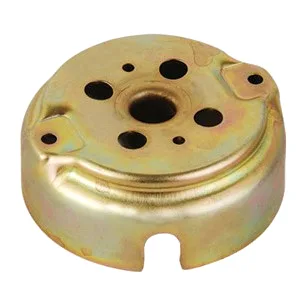
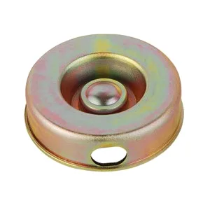
A canned motor cover closes the stator end of a sealless motor — the construction used in canned motor pumps where the rotor spins inside an isolated chamber and no shaft seal exists to leak. The cover’s job is threefold at once: locate the bearing, shield the winding overhang, and hold the boundary the pump’s fluid rating depends on. Aunov Tech draws these covers to print in stainless steel or carbon steel, with bearing seats and spigots machined in-house to ±0.03 mm on the same floor that forms the shell.
Why canned motors put special demands on the end cover
In a conventional motor, the end cover is a mechanical part. In a canned motor, it is part of the pressure boundary — and that changes what “good” means:
- The winding overhang sits behind the cover. The drawn shell shields the end turns from debris and from contact during handling, which matters because a canned motor’s stator is often potted or sleeved — repairs are not a service option.
- Leak paths are the enemy. A welded or seamed cover introduces joints into the boundary; a drawn shell has none on the wall. Where the print asks for it, leak testing is written into the quality plan and the results ship with the batch.
- Fluid compatibility drives the grade. Canned motors circulate the pumped fluid (or a barrier fluid) inside the rotor chamber — 304 / 316 stainless steel is the default for pump duty, and the grade is fixed in the drawing review, not swapped between lots.
The two dimensions that decide fit: bearing bore and spigot
Almost every dimensional problem with an end cover traces to two features, so they get named checks:
- Bearing bore. Drawn to size where the tolerance allows, finish-machined where it does not. Bore size is measured on the CMM at first article and gauged on production runs — it is the seat the bearing actually runs in, not a nominal number.
- Spigot (rabbet) fit. The spigot centers the cover on the motor frame; its runout decides how much of the assembly’s concentricity is inherited from the cover. Spigot runout is a named line on the first-article report.
- Machined vs as-drawn split. As-drawn surfaces hold ±0.1 mm; turned secondary features hold ±0.03 mm. The drawing review decides which feature gets which treatment — machining everything is the expensive way to buy precision you only need in two places.
How the shell is made
Blanks are drawn in stages, with interstage annealing where the wall thins; piercing and trimming run in the same die line. For the deep, slim shells canned motors often need, the draw ratio is checked against the grade at quotation — stainless steel work-hardens faster than carbon steel, so the stage count (and the price) reflects the material, not just the geometry. Process settings are archived with the part number, so nothing depends on the operator remembering; a repeat order starts from the data that already worked. The toolroom detail — die design, wire-cut EDM, maintenance — is on the tool & die design page.
Materials and finishes for pump duty
Stock: SPCC / DC01 carbon steel, 304 / 316 stainless steel, aluminium, brass, copper. For canned motor covers the usual candidates are 304 (general duty), 316 (aggressive or chloride-bearing fluids) and carbon steel where the barrier side is oil-based and dry. Finishes follow the drawing — plating, coating or polishing — and the finish is inspected together with the dimensional report on the first article. Grade reasoning in depth is on material selection & sourcing.
Quality and traceability
Production runs under an ISO 9001 certified system: mill certificates cover every stock delivery, first articles are CMM-measured against the print, and every run is inspected against the first-article report. For this part the named checks are bearing-bore size and spigot runout, plus leak or pressure testing where the pump rating calls for it — the plan is agreed at approval and the batch file carries the results. The system behind this is described on quality control.
Related parts on this site
The wider motor-cover range — starter motor housings, end covers for standard motors, vented shells — is indexed from deep drawn cover and automotive motor components. For enclosure-form shells rather than covers, see deep drawn enclosure.
Requesting a quotation
Send the drawing or a sample with the fluid or environment the cover will see, the annual volume and any leak-test requirement. The quotation returns with a manufacturability review — draw ratio, machined-vs-drawn split, tolerance bands — and the die charge as its own line, via the quote request page. Call-off schedules are supported.
Frequently asked questions
Can the bearing bore be drawn to final size?
When the tolerance band allows it, yes; where the print asks for ±0.03 mm class accuracy, the bore is finish-turned after drawing. The quotation states which features are as-drawn and which are machined, so the cost is visible.
Is leak testing available on the cover itself?
Yes — leak or pressure testing can be written into the quality plan at approval, with results included in the batch paperwork. The drawn wall itself has no seams; the test covers the finished part as machined.
Can you match a cover to an existing motor frame?
Send the frame drawing or a sample cover. It is reverse-measured into a controlled drawing, the bearing bore and spigot are verified on the CMM, and a first article is approved before volume — so the replacement fits the frame it was measured from.
| Item | Canned Motor Cover – Deep Drawn Enclosure |
|---|---|
| Brand | AUNOV |
| Designing | Driven by your drawing or a physical sample — manufacturability review returns with the quotation; revisions re-quoted once, never silently absorbed. |
| Tooling | Die design and toolmaking in house; die charge as its own quotation line, refundable against agreed volumes. |
| Samples | Issued for approval before the run; production starts only after written sign-off. |
| Materials | Carbon steel (SPCC / DC01), 304 / 316 stainless steel, aluminium, brass, copper — grade matched to the fluid and duty. |
| Surface finish | Plating, coating or polishing to suit the drawing; inspected with the dimensional report on the first article. |
| Processing | Progressive drawing through several stages, annealed between draws, trim and pierce in the same die line. |
| Equipment | Mechanical presses 5–250 T plus 250–500 T hydraulics with in-line annealing; secondary ops on CNC turning centres; inspection on the CMM. |
| Tolerance | ±0.03 mm on turned secondary features, ±0.1 mm on as-drawn walls; GD&T per drawing, PPAP-style reports on request. |
| Named checks | Bearing-bore size and spigot runout at first article, gauged on production; leak / pressure testing by agreement. |
| Delivery terms | CIF or DDP, FOB available; T/T or L/C; USD or EUR; call-off schedules supported. |
Related Products
Request a Quote for This Part
Send a drawing or sketch — get material advice, tooling cost and a per-piece price within 24 hours (working days).