
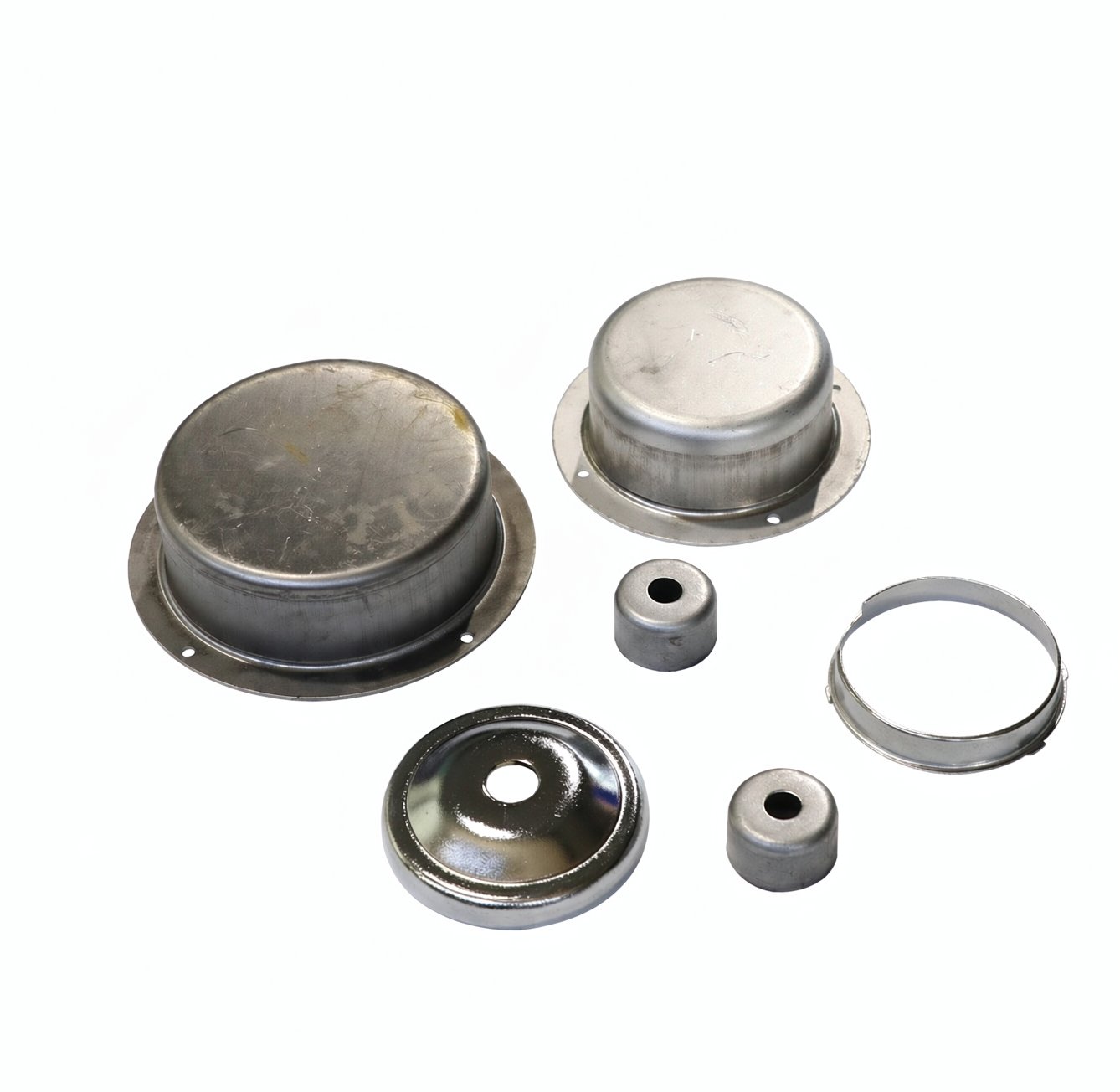
A progressive die is a good way to make a small flat part and a poor way to make a deep drawn one, and most of the trouble with a progressive die on a drawn component comes from the word progressive. It means everything happens in one stroke on one piece of strip, which means every station has to be finished before the part leaves the last one, and it means the strip has to carry enough material for every operation.
A deep drawn part in a progressive die is entirely feasible. What makes it demanding is that a draw introduces variation which every downstream station then has to tolerate, while the strip layout is fixed and cannot absorb it.
What a progressive die actually commits you to
In a progressive tool the strip advances one pitch per stroke, and each pitch puts the part through one more operation. The consequences chain from that:
- The strip layout is a design document. The width carries every feature across the strip; the pitch determines the progression; the scrap skeleton between parts determines the material yield. None of it can be changed without cutting new dies.
- Every station sees every part. A part that fails at station four has been carried through stations five, six and seven, so the failure has already cost more than if it had been detected at station one.
- Material utilisation is fixed by the layout. On a drawn part with a large flange, the flange itself is scrap unless the layout nests parts inside each other’s flanges, which is often geometrically impossible for a round part.
- The operation order is fixed by the pitch. You cannot reorder stations without recutting the die.
This is the real trade. A progressive die has the lowest per-piece cost of any stamping process at volume, and it has the highest tooling cost and the least flexibility. The choice between a progressive tool and a multi-station transfer or a draw-and-trim tool is largely a decision about volume, part size and how much the design is likely to change.
Station order is a technical decision, not a layout convenience
The order in which operations happen changes the result, and the correct order follows a logic.
- Pierce before draw. A hole pierced in the flat blank before the cup is formed ends up in the wall at a position that depends on the draw-in. A hole pierced in the flange after drawing ends up somewhere else entirely. Where a hole must be in a specific place, piercing after the draw is the reliable route.
- Draw before trim. Trimming before drawing removes material that the draw would otherwise have used, so the blank ratio changes and the process has to be re-planned.
- Form the feature before the flange is trimmed. A bend or a flanged edge formed on the strip before trimming behaves differently from one formed after, because the trimming operation leaves a burr on the edge that the forming tool then has to work with.
- Pierce the last if the hole is in a moving wall. A hole pierced in a wall that is subsequently formed will distort with the wall. This is the reason a hole in a drawn cup wall is nearly always pierced last.
Two further practical rules. Anything that leaves a sharp cut edge should be followed by a deburr or a break operation before another forming station uses that edge, because the burr is a tear initiator. And any forming that generates a large force should not be the last station, because a forming last means the part is handled only by its finished feature.
Draw-in variation is what propagates down the tool
A drawn feature’s position depends on how much material fed from the flange, and that depends on blankholder force, friction and material thickness variation — none of which are constant. So the drawn wall’s position varies from part to part, and every station after the draw sees that variation.
On a progressive tool this turns into a running clearance problem. A pilot pin that locates a hole pierced before the draw, for instance, has to tolerate the wall’s movement. A forming tool that closes on a feature whose position varies will either not close on the thick-thickness parts or will overload the thin ones.
The three ways this is managed, in increasing order of cost:
- Clearance-based tolerance. Tools are made loose enough to accept the full variation. This is the cheapest and it produces a part with a correspondingly loose tolerance.
- Locate on the formed feature. Later stations register from the draw rather than from the strip, so variation upstream does not propagate. This requires a pilot on the formed wall and a tool design that can float slightly.
- In-process measurement and adaptive correction. Closed-loop measurement in the tool that adjusts the process. Effective on high-volume automotive work and rarely economic elsewhere.
The middle option is the one worth discussing on a drawing, because it changes what has to be toleranced. If a feature is located from the formed wall, its tolerance is relative to the draw and it is stable. If it is located from the strip, its tolerance includes the draw variation and it is not.
Material thickness variation is the tolerance floor
Coil material arrives with a thickness band, and that band is the ultimate limit on what any stamping process can hold. A mill certificate states a band; the actual material sits somewhere in it.
On a drawn part the thickness band shows up as:
- Draw force variation. Thicker material needs more force. On a press operating near its limit this is the difference between a clean stroke and a stalling or a cracked die.
- Draw-in variation. Thicker material has more friction, so less of the flange feeds in and the wall lands in a different place.
- Wall position after the draw, which is what everything downstream inherits.
- Springback variation. Thicker material springs back more, so a formed feature’s final angle changes across the thickness band.
So a tolerance on a stamped part is really a tolerance relative to the incoming material band. A drawing that specifies a formed angle to a tight band on a thick-gauge material is specifying something the material cannot deliver, no matter how good the tooling is.
Where the material band matters most, the answer is not a tighter tolerance but a narrower material: a specified thickness with a stated band tighter than the mill standard, which is available on request and costs more.
Two materials on one strip: the wear problem
Running aluminium and stainless steel through the same tool is a known and difficult situation, and the reason is the tool surface. Aluminium is soft and it polishes; stainless steel is hard and it abrades. A tool that has been running aluminium develops a polish on the working surface, and that polished surface is softer than the stainless steel that comes next, so the stainless steel begins to wear it. Then the aluminium that follows runs on a worn surface and loses its finish quality.
The practical consequences and mitigations:
- Dedicated tooling per material. The correct answer wherever the volume justifies it. Two tools instead of one is a real cost and it is cheaper than the scrap.
- Tool surface hardness above the stainless steel. A hard insert resists the abrasion but accelerates the galling risk on the aluminium side.
- Restricted lubricant discipline. Different lubricants for the two materials, and an enforced changeover step.
- Batching rather than alternating. Running all of one material then all of the other rather than alternating reduces the number of transitions.
On a drawing for a part made in both materials, the honest question is whether the part is one part number or two. If it is one, the process has to accommodate the material change and the drawing should say so. If it is two part numbers with the same geometry, the tooling question disappears.
What a first article on a progressive tool has to prove
- The whole strip. Not one part from the last station but a full run, because a progressive tool’s faults appear at specific stations and only on parts that have passed through all of them.
- Process capability on the critical dimension. Not a single measured part. On a drawn feature the short-term variation tells you whether the material band and the tool are matched.
- The wall position and thickness after the draw, measured at the corner and at mid-wall, because these drive everything downstream.
- Burr orientation and height on every pierced hole. A burr on the wrong face is a functional defect even when it is within height tolerance.
- Scratch and galling inspection on the formed surfaces, which is where a progressive tool fails cosmetically and where a customer will notice first.
- The scrap skeleton. Confirming that the layout matches the design and that no part is being formed from an already-worked region of the strip.
Questions worth asking about a progressive die drawing
- Is every operation achievable in a single stroke on this strip, and does any feature need a secondary operation?
- For a hole in a drawn wall, is it pierced after the draw, and how is the position toleranced against draw-in variation?
- Do later stations locate from the formed feature or from the strip, and which dimensions inherit draw variation as a result?
- Is the incoming thickness band stated, and are the tolerances achievable across that band rather than at nominal?
- Where the part is made in both aluminium and stainless steel, is it one part number, and is the tooling dedicated per material?
- Are the draw-in compensation and the blank size given as design data rather than left to the press shop?
- Does the first-article requirement cover a full run of the strip rather than a single part?
- Is the inspection plan staged by station, so a defect is attributed to an operation rather than discovered at the end?
The last item is worth insisting on. On a progressive tool, an out-of-tolerance feature found at final inspection could have been caused by any of six stations. Attribute it wrongly and the correction targets the wrong tool, and the problem returns.
Custom Metal Stamping Parts is the parent range for parts like this one; the overview page gathers the tooling logic, finishing options and tolerance notes that apply across the family.
Specifications
| Item | Precision Custom Deep Drawn Stamping Parts Aluminum Stainless Steel |
|---|---|
| Brand | AUNOV |
| Designing | Made to your 2D/3D drawings (PDF, DWG, STEP, IGS) – unusual walls, threads or tolerances are feasibility-checked first; revisions are re-quoted once rather than silently absorbed. |
| Tooling | Tooling is built and held under your part number, so the die charge appears as its own quotation line, and the charge is refundable against agreed volumes. |
| Samples | Free samples are available on standard items, with reports attached. |
| Materials | Stock covers carbon steel (SPCC / DC01), 304 / 316 stainless steel, aluminium and brass; special grades are sourced to the drawing when volumes justify. |
| Surface finish | Plating, coating, anodising or passivation are chosen from the drawing; masking and laser marking are available where the job needs them. |
| Processing | Progressive die stamping, trimmed and formed in one pass; first articles verify the whole flow before the run is released. |
| Equipment | Press shop with 5-250 T mechanical presses and dedicated dies; secondary ops run on CNC turning centres, inspection on the CMM. |
| Tolerance | +/-0.05 mm to +/-0.1 mm across the part; capability is checked on the first article before the run continues. |
| Delivery terms | Terms are FOB by default, with CIF and DDP quoted on request and freight priced to your door. |
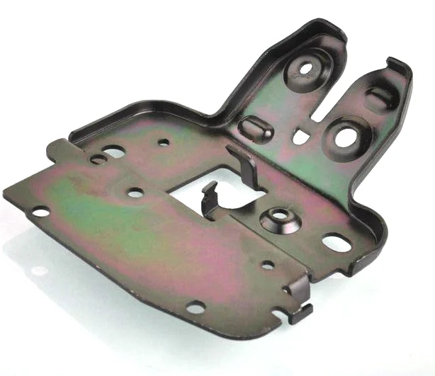
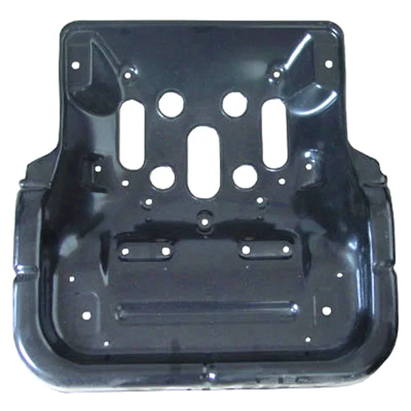
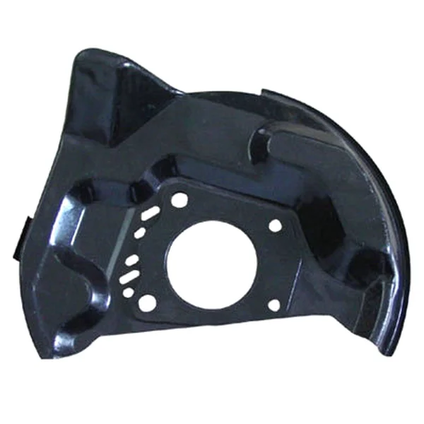
Related Products

Frequently Asked Questions
Why is a progressive die poor for deep drawn parts?
In one stroke on one strip every station must finish before the part leaves, and a deep draw introduces variation that downstream stations cannot absorb from a fixed strip layout.
Can deep drawn parts still be made in a progressive die?
Yes, but the draw is sequenced so downstream stations tolerate the variation, usually by drawing early and stabilizing before the tighter features are cut.
Which materials are stamped?
Aluminium and stainless steel, drawn on mechanical or hydraulic presses with in-process annealing where the alloy’s work-hardening window demands it.
How is consistency held across a long run?
First articles and batch samples are checked on the CMM and the draw is monitored so the formed features stay within the band before the run continues.
Request a Quote for This Part
Send a drawing or sketch — get material advice, tooling cost and a per-piece price within 24 hours (working days).