
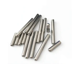
An 8mm probe that is 30mm long, with a flattened closed end, is the geometry of a device that gets pressed into something. The flattening is not a cosmetic finish; it is the interface. It is what makes contact with the surface being measured, and everything about the part — how it is formed, how it is sealed, how it is plated — is decided by the requirement that this small flat face be flat, be clean, and be in metal-to-metal contact.
Copper is chosen for this because it does three things at once: it conducts heat away from the sensing element so the tip reads the process temperature rather than the element’s own, it is easy to deep-draw into a closed cylinder in one operation, and it resists mild corrosion in most process environments without a barrier coating.
Why the end is flattened rather than domed
A formed hemisphere would be stronger and would have better heat transfer. It is rejected for a functional reason: contact.
A flat end makes a defined contact area. Against a flat pipe surface or a tank wall, a flat tip gives a repeatable contact resistance and a repeatable reading. A dome contacts at a point, and point contact is highly dependent on surface finish, alignment angle and how hard the probe is pushed in — so a domed tip reads differently on the same process from one day to the next.
The trade-off is that a flat end concentrates the contact into a small ring around the edge. This puts two constraints on the part that do not exist for a domed version:
- Flatness. The contact face has to be flat within a stated band, otherwise the probe rocks and reads high or low depending on which edge is loaded. A face flatness of a few micrometres over an 8mm disc is a demanding machining target.
- Edge condition. The perimeter where the flat meets the wall is the point of highest stress and of highest wear. It must be a small, consistent break — sharp enough to be clean, rounded enough not to cut the mating surface or leave the contact ring undefined.
This is why the flattened end is the feature that most often gets an inadequate specification. A drawing that says “flat end” without a flatness band, without a dimensional reference and without an edge treatment has specified the shape but not the function.
Deep drawing in one operation puts the whole wall in a work-hardened state
A closed-end tube of this proportion is typically made in a single deep-drawing operation from a blank, or in two with an intermediate anneal depending on the ratio. The dimensional outcome depends entirely on the material condition entering the die.
Three material states get specified in practice, and each one produces a different part:
- Annealed copper (O temper). The correct starting condition for a demanding draw. High ductility, low flow stress, and the resulting wall can be thinned toward the base of the cup. This is the version to specify when the end-to-body transition is tight or the diameter ratio is aggressive.
- Quarter-hard / half-hard. Drawn with less intermediate annealing. Faster and stronger in the finished body, but the draw window narrows and the wall thinning is less predictable.
- Full hard. Only sensible where no further forming is required. If any flaring, bending or a secondary closure is needed downstream, full hard will crack at the transition rather than form.
The consequence is that the temper condition belongs on the drawing as a stated requirement, not as something the material mill decides. Two suppliers using nominally identical copper will produce visibly different tips from different tempers.
Wall thickness thins where you least want it to
In deep drawing, material flows radially from the blank into the cup wall, and the flow is not uniform. The wall thins most at the corner between the cup floor and the cylindrical wall, because that is where the material has travelled furthest and been stretched most.
On a part that will be pressed against a hot vessel, this matters in two ways:
- Thermal conduction. A thinned corner conducts less. If the thinning is variable around the circumference, the reading changes with probe rotation — a frustrating field fault that looks like an intermittent sensor problem.
- Mechanical robustness. The corner is simultaneously the thinnest, the most work-hardened and the most highly stressed section. It is where the probe fails if it is dropped, if it is inserted against an obstruction, or if it is repeatedly inserted and withdrawn.
The drawing should therefore carry two wall figures: the nominal body wall, and a minimum wall at the end-to-wall transition. The minimum is the one that gets measured on a sectioned first article, because it cannot be measured on the finished part by any non-destructive means that a supplier can run at production rate.
Plating interacts badly with a contact face
Copper probe tips are usually plated — tin, nickel or a combination — for corrosion resistance and for solderability of an attached lead. On a probe, plating is mandatory in most cases, and it introduces one specific problem.
The plated layer sits on the contact face. Its thickness is a few micrometres to perhaps twenty, and it changes the contact geometry in two ways:
- Plating on the flat face reduces its flatness, because plating builds up preferentially on high points and edges. A face that was flat to five micrometres can be less flat afterwards.
- The edge radius, if not masked, grows a burr-like lip that defines the contact ring and can be sharp enough to mark the mating surface.
The fix is standard practice and should be stated on the drawing: mask or hand-polish the contact face and the edge break after plating, or plate only the barrel and the base. Whichever is chosen, the drawing should say which, because “plated per standard” leaves it to the plater.
How a probe tip is actually sealed to its lead
The probe is a closed copper cup, so the lead has to get in somehow. Two routes dominate and they suit different service conditions.
Glass-to-metal hermetic seal. The lead passes through the base of the cup as a matched-metal-glass pinch through which the lead is drawn. This is a true hermetic seal with an extremely low leak rate and a wide temperature capability, and it is what makes a probe usable inside a hermetic or pressurised system. It costs more and it requires the cup base to be positioned and annealed correctly.
Epoxy or cement fill. The cup is filled or the rear is potted with a thermal filler and the lead is embedded in it. Simpler and adequate where the pressure boundary is not required to hold refrigerant. Its limits are the filler’s temperature rating, its tendency to shrink over thermal cycling, and the fact that a filled probe transfers heat through the filler to the lead — the lead becomes a heat path that partly defeats the point of the copper tip.
Whichever is used, the thermal contact between the sensing element and the inside of the closed end is a separate design question. Copper conducts well, but air does not. If the element sits on a stand-off rather than in contact with the end wall, the probe reads several degrees high, consistently and irrecoverably. Contact paste, a clamped element or a filled cavity are the usual answers.
Acceptance testing that reveals the real faults
- Face flatness and parallelism to the axis. Checked on a surface plate or granite, or optically. This is the primary functional dimension.
- End length from the datum. If two probes of the same nominal part are inserted to the same depth, their tips must be at the same height, or readings differ.
- Sectioned first article. Minimum wall at the transition, corner radius, and evidence of the temper condition. This is a first-article check, not a production one.
- Continuity and insulation resistance between the lead and the case, at temperature and at humidity rather than only in the lab.
- Functional temperature check. Immerse or contact against a traceable reference and confirm the reading against the element’s specified curve for the installed thermistor type.
- Corrosion resistance. For a plated tip, a salt spray or humidity test confirms the plating is continuous — a pinhole at the edge break is where corrosion starts and it is invisible.
Questions worth settling on this drawing
- Is the flatness of the contact face specified as a band referenced to the probe axis, rather than implied by the word “flat”?
- Is the edge break between the flat and the wall dimensioned, and is it masked from plating?
- Is a minimum wall specified at the end-to-wall transition, distinct from the body wall?
- Is the temper condition called out — annealed, quarter hard or half hard — and is the draw route agreed with it?
- Is the seal type stated as a requirement, hermetic or filled, together with its temperature rating?
- Is thermal contact between the element and the end wall specified, or is it assumed from the copper?
- Does the drawing identify which surfaces are contact surfaces, so that plating, masking and polishing all act on the same list?
That last item is worth more than its apparent simplicity. Most tip-related returns come not from a wrong dimension but from three suppliers each correctly interpreting an incomplete drawing: one polished the face, one plated over it, one masked it. Marking the contact surfaces once, on the drawing, removes the entire category.
This part belongs to our Deep Drawn Tubes & Sleeves range. The deep drawn tubes & sleeves pages collect the process notes, common materials and inspection points behind every product in the family.
Specifications
| Item | Custom deep drawing 8X30mm flattend end closed copper tube sensor probe |
|---|---|
| Brand | AUNOV |
| Designing | The quotation follows your print, not a catalogue – unusual walls, threads or tolerances are checked for feasibility first. |
| Tooling | Tooling is built and held under your part number, so no tooling step is outsourced, and ownership is confirmed on the quotation. |
| Samples | First-article samples ship with a dimensional report and material certificate, so the approved first article becomes the gauge reference, and the signed sample is kept for future reorders. |
| Materials | Copper T2 / T3, annealed for forming; conductivity and grain data recorded per production lot. |
| Surface finish | Zinc, nickel or chrome plating, anodising, passivation or e-coat; finish thickness and adhesion checked on the first article. |
| Processing | Tube drawing, straightening and turning in one flow; every stage is logged against your part number. |
| Equipment | Drawn-tube benches, in-line annealing and CNC turning, backed by CNC turning centres and a climate-controlled inspection room. |
| Tolerance | +/-0.03 mm on machined ends, straightness per print; finer bands confirmed from capability data before quoting. |
| Delivery terms | FOB, CIF or DDP per Incoterms 2020, T/T or L/C, with D/P accepted on repeat business; each volume tier carries its own quoted price. |
Related Products


Frequently Asked Questions
Why is the end flattened rather than domed?
An 8 mm probe that is 30 mm long with a flattened closed end is the geometry of a device that gets pressed into something, and the flattening is not cosmetic, it is the interface. It is what makes contact with the surface being measured, and everything about the part is decided by the requirement that this small flat face be flat, clean, and in metal-to-metal contact. A dome contacts at a point, and point contact depends heavily on surface finish, alignment and how hard the probe is pushed in.
What does a single deep draw do to the wall?
A closed-end tube of this proportion is typically made in one deep-drawing operation from a blank, or in two with an intermediate anneal depending on the ratio. In deep drawing the material flows radially from the blank into the cup wall, and the flow is not uniform, so the wall thins where you least want it to. Two suppliers using nominally identical copper produce visibly different tips from different tempers.
Why does plating interact badly with a contact face?
Copper probe tips are usually plated, tin, nickel or a combination, for corrosion resistance and for solderability of an attached lead, and on a probe plating is mandatory in most cases. The problem is that plating on the flat contact face changes that metal-to-metal interface, so the fix is to mask or hand-polish the contact face and edge break after plating, or plate only the barrel and the base. That fix should be stated on the drawing.
How is the lead brought in and the probe sealed?
The probe is a closed copper cup, so the lead has to get in somehow, and the cup is filled or the rear potted with a thermal filler with the lead embedded in it. The limits are the filler’s temperature rating, its tendency to shrink over thermal cycling, and the fact that a filled probe transfers heat through the filler to the lead, which becomes a heat path that partly defeats the copper tip. Whichever is used, the thermal contact between the sensing element and the inside of the closed end is a separate design question.
Request a Quote for This Part
Send a drawing or sketch — get material advice, tooling cost and a per-piece price within 24 hours (working days).