

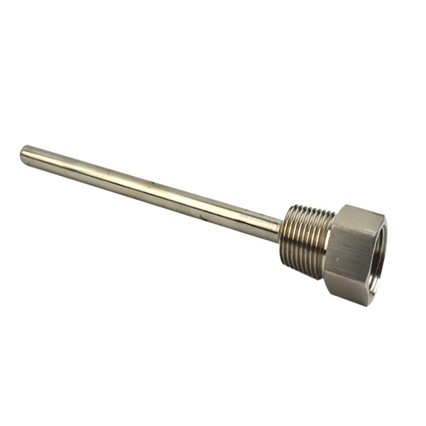
A deep-drawn temperature probe housing is the part where the drawing’s geometry and the drawing’s tolerance are pulling in opposite directions, and the reason is specific: on a probe, the accuracy is set by a dimension that the press produces and the machining does not control. Insertion depth is a tooling output. It is also, on most probes, the largest single error term. So the number that matters most is the one nobody owns.
Drawn shell with machined seats and threads where the print calls for them, at +/-0.02 mm on machined seats and sealing faces flat to drawing. So the tight band is on the machined features and the accuracy parameter is elsewhere – which is why this page is about the relationship between the two.
The conduction error is the dominant one on an insertion probe
- The temperature gradient runs from the process along the tube toward the mounting end. The sensor reads somewhere between the process temperature and the ambient, displaced toward the process. That displacement is the dominant error on most insertion probes and it scales with how much of the tube is outside the process.
- So the number that matters is not the overall length – it is the length that will actually be immersed. And the two are different numbers, because the probe is installed into something – a port, a vessel, a nozzle – and only part of it enters the process.
- Which means the drawing has to carry both, and the second one is a customer-interface dimension rather than a part dimension. Where it is missing, the probe is made correctly and reads wrongly, and there is no inspection that would find it because the part is to drawing.
So what does the drawing actually control?
Three things, and each one is a mitigation rather than a fix.
- Length from the sealing face to the tip, as a functional dimension with a tolerance. It will not by itself hold the error to a target, but it holds the probe’s calibration consistent, and a consistent probe can be calibrated once.
- The sealed length – the part of the tube that is not in the process. This is the number that sets the error and it belongs on the drawing as a stated design intent. Where it can be reduced on the customer’s side – by using a shorter port, or a compression fitting rather than a long threaded boss – it reduces the error without changing the probe at all.
- And the thermal path along the tube. A thicker wall and a poorly conductive alloy flatten the gradient and reduce the error, at the cost of the response time. That trade is the design, and it is worth stating explicitly on the drawing because it is the reason for the wall’s dimension.
Why a deep-drawn probe is harder than a machined one
- The closed end’s thinning. The punch nose stretched the metal at the tip, so the tip is the thinnest section of the pressure boundary and – on a probe – the tip is also where the thermal contact with the process happens. So the tip’s minimum wall is a specification and it is checked at the tip.
- The corner’s condition. The drawn corner is the most heavily worked metal on the part and it carries the most residual stress. On a probe installed into a port, the corner is where the installation’s stress concentrates – it is often where the tube is gripped, or where the sealing surface meets the tube. So the corner’s radius is a durability parameter and not just a forming one.
- And the tube’s straightness. A drawn tube is straight, but a long thin tube will be straight as delivered and bent as installed. So on a long probe the straightness tolerance has to be good enough that the bend required to install it is well below the tube’s minimum bend radius.
The sealed end, which on this part is a specific decision
Deep drawing with CNC turning for finishing. So the tip is a drawn closed end, and everything about a drawn tip is set by the drawing operation. Three choices, and they trade against each other.
- A drawn closed end is the economical route and it gives a tip that is thinner than the nominal wall. On a low-pressure probe that is entirely adequate, and it is the normal answer.
- A heavier tube with a welded tip is the answer where the pressure, the temperature or the corrosion demands a heavier wall than the drawing can give. On a high-temperature probe a heavier wall also reduces the conduction error, so this route serves accuracy and pressure at the same time – at the cost of a weld in the boundary and a slower response.
- A machined solid tip is the answer where the tip’s geometry is functional – where the tip is a flat, a cone, or a shaped element that touches a surface – and it is also the most expensive.
Material, and the thermal argument
Mill certificates and heat numbers on the first article. Carbon steel, 304 and 316 stainless steel, aluminium and brass. On a probe the material is chosen by three things and the second one is specific to this part.
- Corrosion from the process inside – 316L for chloride-bearing and for cleaning regimes, and the L grade where the tip is welded.
- And the thermal conductivity, which on a probe is an accuracy parameter rather than a general property. A conductive wall carries heat from the process toward the mount and increases the error. So on a high-accuracy probe a less conductive material can be the better choice, and that is counter-intuitive enough to be worth stating on a drawing.
- And the process side’s chemistry is not the only consideration – where a probe sits in a food or a pharmaceutical application, the tip’s surface condition is a documented, inspected, product-contact surface with its own passivation record, and that is a separate specification from the tube’s material.
Only one of the two sets of numbers appears on the drawing
+/-0.02 mm on machined seats and sealing faces flat to drawing, with capability checked on the first article. On this part the tolerance scheme has to be read as two sets, and only one of them is on the drawing.
- The drawing’s set: the sealing face’s flatness and perpendicularity, the thread, any spigot or gland’s diameter and depth, and the bore’s concentricity to the sealing face.
- The tool’s set: the closed end’s minimum wall, the wall’s uniformity, and the tip’s position – which are press outcomes and which have to be specified as process capabilities rather than as machined dimensions.
- And the customer’s set: the immersion depth and the sealed length, which are not part of the part at all and which determine the accuracy. This is the set that has to be on the drawing as a stated requirement even though it is not a dimension of the part.
The drawing’s dimensions are conventional, the tool’s are a process check
First articles and batch samples on the CMM. On a probe the inspection plan has a specific weak point and it is worth naming.
- The drawing’s set is inspected conventionally.
- The tool’s set is inspected as a process check – the tip’s minimum wall on a first article and periodically, and the wall’s uniformity at the corners.
- And the customer’s set cannot be inspected at all, because it is not a property of the part. Which means the only way to close that gap is to state it on the drawing, and that is why it belongs in the specification rather than in a conversation.
How much of this probe actually sits in the process?
How much of this probe will actually be inside the process when it is installed? It sounds like a trivial question and it is the one that determines whether the probe meets its accuracy, and it is almost never asked – because the person specifying the probe knows the probe’s length and the person installing it knows the port’s depth, and nobody connects them. Where it has not been connected, the error is often several times the probe’s stated accuracy, and it will present as a calibration problem rather than as a design problem. There is a second question that is worth asking at the same time and that decides the probe’s construction rather than its accuracy: what pressure and temperature does the tip see? Because that decides whether the tip can be a drawn closed end – which is economical and accurate in its own way – or whether it has to be a heavier gauge with a welded or machined tip, and on a high-temperature probe that heavier tip also reduces the conduction error. So one question about the installation sets the accuracy, and one about the service sets the construction, and both of them are worth more on the enquiry than any dimensional detail.
You will find this part in our Sensor Housings range. Process notes, common materials and inspection points for every product in the family are collected across the sensor housings pages.
Specifications
| Item | Stainless Steel Mini Stepped Housing with Top Port |
|---|---|
| Brand | AUNOV |
| Designing | Quotation reflects the real drawing: tolerances, finish and features are priced as specified. |
| Tooling | Our toolroom covers die design, wire-cut EDM and maintenance, so die cost stays transparent, and the charge is refundable against agreed volumes. |
| Samples | Approval is in writing, and the signed sample is kept as the reference for repeats. |
| Materials | Stock covers carbon steel (SPCC / DC01), 304 / 316 stainless steel, aluminium and brass; mill certificates and heat numbers accompany the first article. |
| Surface finish | Surface treatment matched to the duty: plating, coating or polishing; finish thickness and adhesion checked on the first article. |
| Processing | Drawn shells receive machined seats and threads where the print asks; filed batch records let a repeat order start from approved data. |
| Equipment | Hydraulic presses for drawing, with CNC turning for finishing; first articles and batch samples are checked on the CMM. |
| Tolerance | +/-0.02 mm on machined seats, sealing faces flat to drawing; capability is checked on the first article before the run continues. |
| Delivery terms | FOB Ningbo or Shanghai, T/T or L/C, with D/P accepted on repeat business; repeat orders reuse the approved first article. |
Related Products


Frequently Asked Questions
Why is a deep-drawn probe’s accuracy owned by a dimension nobody controls?
Insertion depth is a tooling output that the press produces and the machining does not control, and on most probes it is also the largest single error term. The drawing’s dimensions are conventional, the tool’s are a process check, and only one of the two sets of numbers actually appears on the drawing. That mismatch is why a correctly made probe can still measure the wrong temperature.
How is the sealed tip decided on a deep-drawn probe?
The tip is a drawn closed end, and everything about a drawn tip is set by the drawing operation. Whether it can stay a drawn closed end, which is economical and accurate in its own way, or must become a heavier gauge with a welded or machined tip depends on the duty. On a high-temperature probe that heavier tip also reduces the conduction error.
Why is a deep-drawn probe harder than a machined one?
Because the accuracy is set by a dimension the press produces, so the geometry and the tolerance are pulling in opposite directions. Drawn shell with machined seats and threads where the print calls for them runs at +/-0.02 mm on machined seats and sealing faces flat to the drawing, with capability checked on the first article. Deep drawing with CNC turning handles the finishing.
What should the drawing say about the material and the immersion?
Material is chosen on the thermal argument as much as the barrier one, with carbon steel, 304 and 316 stainless steel, aluminium and brass held. The question that matters most is how much of this probe actually sits in the process, because the answer changes the conduction error more than any tolerance on the drawing. Only one of the two sets of numbers appears on the drawing, and it is not the one that decides accuracy.
Request a Quote for This Part
Send a drawing or sketch — get material advice, tooling cost and a per-piece price within 24 hours (working days).