

A thermocouple protection tube has a requirement that no other temperature sensor housing has, and it is not about temperature at all: the tube must not create a junction of its own. A thermocouple measures the difference in EMF between two dissimilar metals, and every dissimilar-metal junction anywhere in the measurement circuit contributes its own EMF. So a protection tube that is electrically continuous with the thermocouple’s wires – which is the normal case – will generate its own spurious signal if any current flows along it, and if the tube and the wires are dissimilar metals there will be a thermally-generated EMF at the junction between them.
That single electrical fact is what separates a thermocouple protection tube from every other sensor housing on this site, and it drives almost everything on this page.
The two junction rules
- No junction between the tube and the wires. The wires must not touch the tube anywhere along their length inside the tube. The tube is there to isolate the wires from the process, and if the wires touch the tube the isolation is gone and the tube’s own material enters the measurement circuit.
- No junction between dissimilar metals in the hot zone. If the tube is stainless steel and the wires’ insulation or their transition to bare conductor is within the temperature gradient, that junction produces an EMF that changes with temperature and with how much of the tube is inside the process. This is the error that a thermocouple installation on a badly designed tube produces, and it is not a manufacturing defect – it is a design defect that no amount of careful making will fix.
So on this part the design question is: how are the wires suspended inside the tube, and where does the transition to the thermocouple’s junction happen? A ceramic insulator, a MgO filling, a loose wire inside a well – these are the arrangements, and each one puts the wire-to-junction transition at a different place.
Why a thermocouple needs protection at all
Because the wires are thin, they are copper or nickel or inconel, and none of those survives most process environments. So the protection tube carries the process and the wires ride inside it, thermally insulated from it.
- That insulation is the whole point, and it means the tube’s wall is chosen so that the temperature gradient from the process to the junction is reduced. On a tube used in a liquid or a gas, the process temperature is carried by the tube’s material and the wires see a temperature closer to the mount’s.
- Which means the tube’s conductivity and thickness are accuracy parameters, and on an insertion thermocouple the tube is deliberately heavy – heavier than the accuracy would require – precisely to flatten the gradient.
- And that same gradient is what creates the junction error if the tube is dissimilar to the wires. A thin, conductive tube makes the gradient small; a heavy tube makes it smaller. So a heavier tube is a more accurate tube for junction reasons and for conduction reasons, and the two reasons point the same way.
Insertion depth and the error budget
Deep drawing on hydraulic presses, CNC-finished where tolerances tighten, at +/-0.01 mm on sealing faces and +/-0.05 mm on drawn profiles. On a thermocouple tube the tight band’s destination is correct – the sealing face is what holds the process out – but the accuracy is set by something that does not appear there.
- Immersion depth. The temperature gradient runs from the process along the tube toward the mount, and the junction sits somewhere in that gradient. So the error is a function of how much of the tube is inside the process and how much is out. A tube in a vessel that only accepts half its length is a different sensor from a tube in a vessel that takes all of it.
- And the response time, which is a function of the same tube’s mass. A heavier tube is more accurate and slower, and this is the same trade that appears on every thermowell page – it never resolves, it just has to be chosen.
- The conduction error and the junction error are additive, and on a badly designed tube the junction error dominates. So a tube that is specified only for its accuracy at one temperature is a tube whose total error is unknown at every other temperature, because the junction error scales with the gradient.
Electrical continuity, and the one that is not always wanted
There is a specific design decision here that is worth naming because it is the opposite of what most people assume.
- An ungrounded thermocouple, where the tube is electrically isolated from the wires, is what most installations require and what most protection tubes are designed for. The tube is a purely mechanical and thermal part.
- A grounded thermocouple, where the tube’s end is welded or filled to the junction’s sheath, is used where a grounded junction is wanted for mechanical strength or for noise reasons. Here the tube IS in the circuit, and the tube’s material has to be compatible with the sheath’s.
- And a grounded tube used on an ungrounded junction is a defect that will show up as an intermittent, temperature-dependent measurement error rather than as an obvious failure. So the drawing has to state whether the tube is a grounded or an ungrounded design, and that is a functional specification not a construction detail.
A protection tube’s third material requirement is the one missed
Carbon steel, 304 and 316 stainless steel, aluminium and brass, with material substitutions proposed only in writing. On a protection tube the material has three jobs and the third is the one that gets missed.
- Corrosion, from the process inside. 316L for anything chloride-bearing, and the L grade if the tube will be welded – and a protection tube is frequently welded to a mounting flange or to a fitting, which makes the L grade relevant on most of them.
- Thermal conductivity, for the gradient. Stainless Steel is a poor conductor, which on an insertion thermocouple is actually useful – a poor conductor flattens the gradient along the tube and reduces the conduction error. So on a thermocouple tube, stainless steel’s poor thermal conductivity is an advantage and on a resistance thermometer it is a disadvantage, and the same reasoning gives opposite answers on two parts that look identical.
- And compatibility with the thermocouple’s sheath, which is the requirement that is genuinely easy to miss. If the tube is in electrical contact with a thermocouple’s metal sheath – a grounded junction, or a tube whose end touches the sheath – then the tube’s alloy and the sheath’s alloy form a junction, and a common sheath is a nickel-chromium alloy that is dissimilar to the tube’s stainless steel. So a grounded thermocouple’s tube has to be specified against the sheath’s material, not just against the process.
A protection tube’s finish is decided by its inside and its seal
Plating, powder coating, anodising or polishing per the print, with masking and laser marking available. On a protection tube the finish requirements are narrow and all of them are about the inside or about the seal.
- The sealing face, unmasked – it is the process boundary.
- And the tube’s interior, where it matters. On a thermocouple tube the interior is the gas or the insulation fill that surrounds the wires, and it has to be clean and free of any residue or oil, because any of it will contaminate the fill or the wires and can create its own thermal or electrical effect. So the interior’s cleanliness is a requirement on a drawn-and-machined part and it should be stated.
- The exterior is conventional corrosion protection, and on an insertion tube that will be handled during installation, a coating that chips at the grip area is both cosmetic damage and a corrosion initiation site.
Three flagged dimensions here, and the accuracy is not among them
+/-0.01 mm on sealing faces and +/-0.05 mm on drawn profiles, with finer bands confirmed from capability data. On this part the flagged dimensions are three and the accuracy parameter is not among them.
- Sealing face: flatness and perpendicularity, measured as two values.
- Bore concentricity to the sealing face, where the tube is located by its outer surface or by a spigot – because a tube that is eccentric in its mount will read slightly differently at different immersion depths.
- Length, as a functional dimension with a tolerance, because it is the immersion depth that sets the error budget.
- And the requirements that are not dimensions: whether the tube is grounded or ungrounded, the tube’s bore diameter relative to the thermocouple’s sheath, and the cleanliness of the interior. Those three determine whether the part measures correctly and none of them appears as a tolerance.
Grounded or ungrounded, and what is the sheath made of?
Is this thermocouple grounded or ungrounded, and what is its sheath made of? Two questions, and they decide the tube’s material, the tube’s interior, and whether the tube is in the measurement circuit at all. An ungrounded tube is a purely mechanical part and can be specified against the process alone. A grounded tube is in the circuit, and its material has to be compatible with the sheath – and if the sheath is the common nickel-chromium alloy, then the tube cannot be an ordinary stainless steel without creating a junction inside the temperature gradient. That question is almost never asked at enquiry, because the buyer thinks of the tube as a piece of pipe and the sheath as the customer’s business, and the junction between them is nobody’s business until the readings are wrong. There is also a second question worth asking because it decides the tube’s dimensions and it is the one the drawing usually gets wrong: how much of this tube will actually be inside the process? Because a tube specified at 150 mm that gets 60 mm of immersion is a different sensor from the one that was specified, and the error difference can be larger than the entire accuracy claim – and nothing on the part will reveal it, because the part is made correctly.
Sensor Housings is the parent range for parts like this one; the overview page gathers the tooling logic, finishing options and tolerance notes that apply across the family.
Specifications
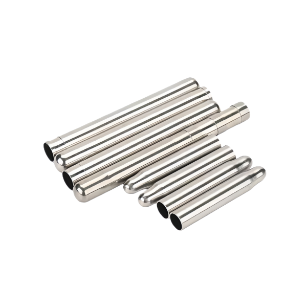
| Item | Stainless Steel Open-Top Cylinder with Base Flange |
|---|---|
| Brand | AUNOV |
| Designing | Driven by your drawing or a physical sample – unusual walls, threads or tolerances are feasibility-checked first; the same drawing is used for every repeat order. |
| Tooling | Die design and toolmaking stay in house, so no tooling step is outsourced, and maintenance is tracked against the part number. |
| Samples | Sample parts are measured and reported before submission, so the part is proven before it is made in volume, and mass production is gated on that approval. |
| Materials | Carbon steel, 304 / 316 stainless steel, aluminium and brass are all held in stock; material substitutes are proposed only with your written approval. |
| Surface finish | Plating, powder coating, anodising or polishing, per the print; masking and laser marking available where needed. |
| Processing | Deep drawing on hydraulic presses, CNC-finished where tolerances tighten; in-process checks sit between stages, not only at the end. |
| Equipment | Deep drawing presses plus CNC turning centres for machined faces, with CNC turning centres for secondary operations and CMM inspection. |
| Tolerance | +/-0.01 mm on sealing faces, +/-0.05 mm on drawn profiles; finer bands confirmed from capability data before quoting. |
| Delivery terms | Terms are FOB by default, with CIF and DDP quoted on request and freight priced to your door. |
Related Products


Frequently Asked Questions
Why must a thermocouple protection tube not create a junction of its own?
A thermocouple measures the difference in EMF between two dissimilar metals, so the tube must not add an EMF of its own to the measurement circuit, or it generates a spurious signal if any current flows along it. The wires are thin copper, nickel or inconel, and none survives most process environments. Deep drawing on hydraulic presses, CNC-finished where tolerances tighten, runs at +/-0.01 mm on sealing faces and +/-0.05 mm on drawn profiles.
What is the third material requirement a protection tube is usually missed on?
A grounded tube is in the circuit, so its material has to be compatible with the sheath; if the sheath is the common nickel-chromium alloy, an ordinary stainless steel tube would create a junction inside the temperature gradient. Carbon steel, 304 and 316 stainless steel, aluminium and brass are held, with substitutions proposed only in writing. Plating, powder coating, anodising or polishing is per the print.
How does insertion depth dominate the error budget?
A tube specified at 150 mm that gets 60 mm of immersion is a different sensor from the one specified, and the error difference can be larger than the entire accuracy claim. Nothing on the part reveals it, because the part is made correctly. Insertion depth is therefore an accuracy parameter, not just a fit dimension.
Grounded or ungrounded, and what is the sheath made of?
Those two answers decide whether the tube is electrically in the circuit and which alloy it can be. Grounded or ungrounded, and what is the sheath made of, is the question to settle before the tube is specified. Sensor Housings is the parent range for parts like this one.
Request a Quote for This Part
Send a drawing or sketch — get material advice, tooling cost and a per-piece price within 24 hours (working days).