

An automotive oil pressure sensor is a part that lives in an engine bay, and the engine bay is a worse environment than almost anything else a sensor gets: it is hot, it is vibrating continuously, it is full of oil mist and salt and road debris, and it is expected to work for years. So the housing is not primarily a pressure boundary on this part – it is a mounting and a thermal problem, and the pressure function is the easy half.
Drawn shell with machined seats and threads, +/-0.01 mm on turned or milled features and +/-0.03 mm on formed details. The interesting requirement on a part like this is not where the tight band goes – it obviously goes on the machined features – but what has to happen to the sensor’s reading because the housing is doing something thermally.
An engine bay is three hostile environments at once
An oil pressure sensor’s housing faces heat, vibration, and corrosion, and each one produces a failure mode that is specific and predictable.
- Heat, and the measurement problem it creates. An engine bay’s temperature swings enormously between cold start and full load. If the sensor’s sensing element is not at the oil temperature, the reading is wrong – and on a pressure sensor the error is often worst exactly when it matters, because the conditions that change the reading are the same conditions that change the oil pressure. So the housing’s job includes thermal management, and the first question is what the reading is supposed to be relative to.
- Vibration, and it arrives at the mounting. A sensor on an engine is on a vibrating structure continuously. The failure sequence is usually: the mounting loosens, the shell’s walls fatigue at the root, a crack opens at the mounting boss or at the drawn corner, and the oil gets in. So the mounting’s geometry and the drawn corner’s condition are the durability requirements, and neither one is dimensional.
- Corrosion, and it enters through the cable entry. The seal that stops oil at the sensor is the same seal region, but the cable entry is the one that fails in service because water and salt get into it and wick up the cable. That is the classic automotive sensor failure mode and it is a design problem, not a workmanship one.
So the housing’s four jobs are: hold pressure, carry the heat away from the element so the reading is right, survive vibration without a fatigue crack, and keep water out of the cable entry. The last two are the ones that decide the part, and neither is a tolerance.
The mounting, which is where this part actually lives
An automotive sensor is mounted, and the mount is a load path and a heat path at the same time. Four considerations, all of them specific to this duty.
- A threaded mount into the engine block is a heat path and a pressure boundary together. The sensor screws into a port, that port is part of the engine casting, and the casting is part of the engine’s heat rejection. So heat flows from the engine through the sensor’s thread into its body – which is the wrong direction, because it warms the element and shifts the reading. A mounting that isolates thermally and a mounting that is strong enough to hold the sensor are in tension, and the answer is usually a shoulder that carries the load and a thread that is thermally broken, or a mount that takes the load on a face rather than on the thread.
- The mounting’s mechanical integrity. An oil pressure sensor sees pressure pulses – on a diesel engine, on a start-stop system, and on any engine where the oil pressure varies rapidly – and it sees vibration. Both load the mount, and both load it cyclically. So the mount’s thread engagement and the shell’s wall around it are both fatigue cases.
- A torque-specified installation is normal on an automotive part, and it has a consequence: the thread has to seal without relying on a sealant, and the port has to be clean. A thread design that needs PTFE tape is a thread design that will be installed wrong in a factory.
- And the mounting’s flatness is the tightest dimension on the housing. A sensor that does not sit square on its port face is not sealed, and it is also not thermally coupled – so the same flatness is a seal requirement and an accuracy requirement.
The cable entry, which is the real failure mode
On an automotive sensor the cable entry is where almost all of the field failures happen, and the reason is that it is a place where three different requirements meet and none of them wins on its own.
- It has to hold pressure, or at least the oil mist pressure, against a low-pressure seal. The seal is usually an O-ring or a moulded gland around the cable, compressed by the housing’s shoulder. That seal’s compression is set by the housing’s internal geometry, not just by the gland, which is why the gland’s depth and the housing’s internal step are a matched pair.
- It has to keep water out over years. A seal that would pass a bench water test can fail after two winters of thermal cycling, because the elastomer’s compression set grows as it is heated and cooled, and because the cable itself is a capillary that will wick water into the housing if the seal has let any in. On a design that has to survive a service life, the answer is usually a barrier design – the housing seals onto the connector or onto a moulded boot, and the cable’s own jacket is outside that seal entirely.
- And it has to let the cable through without crushing it. The gland has to hold the seal and not damage the cable’s insulation or its conductors, which is a tight-tolerance hole that is also a soft-material problem.
So on this part the cable entry’s design is: how the cable is sealed, what it is sealed against, and whether the seal is in the housing or in a connector. That decision is worth making before the housing is drawn, because it determines the housing’s end geometry, the thread or the bayonet that holds the connector, and whether the housing is a single part or a part plus a moulded boot.
Material, and the automotive-specific requirements
Carbon steel, 304 and 316 stainless steel, aluminium and brass are held on site, with material substitutes proposed only with the written approval. On an automotive sensor the grade is chosen by three things and one of them is not engineering.
- The fluid. Engine oil at temperature is benign to stainless steel, so 304 or 316L is normal and the choice between them turns on whether the sensor sees road salt – which it does, from underneath.
- The heat. An engine bay’s temperature, on a sensor that reads correctly, needs an alloy with a defined high-temperature behaviour. Stainless Steel is the normal answer and it is comfortable there.
- And the galvanic coupling that nobody specifies. A stainless steel sensor threaded into an aluminium engine casting is a galvanic couple at exactly the place where oil and salt both are. In most vehicles this is tolerated – the sensor is a small area and the casting is large – but on a part that has to survive years, it is worth deciding deliberately: either isolate the sensor’s thread with a coating or a seal, or accept it and note it.
- Aluminium is used where thermal mass must be low – a sensor that has to respond quickly wants a light housing – and it is the right answer on a fast-response oil temperature sensor. Its consequences are the expansion mismatch with a steel connector and its poor galling behaviour on a threaded mount.
- Brass is used where a plated exterior and good machinability matter and where the temperature is moderate, and its limitation in an oil that is hot and aggressive is dezincification, which on a long-life automotive part is a real risk.
An automotive sensor is finished for hands and for road salt
Zinc, nickel or chrome plating, anodising, passivation or e-coat, with the finish inspected with the dimensional report on the first article. On an automotive sensor the finish requirement is mostly about the surfaces that a customer’s hands and a car’s underbody touch.
- The thread, masked or specified post-finish with an allowance. On a thread-sealing sensor mount a plated thread changes the fit and it will flake at the roots, and the flakes go into the engine.
- The sealing face at the mount, unmasked. It is both a seal and a thermal couple, and a coating on it is a coating on both.
- The cable entry’s gland, unmasked. A coated gland changes the seal’s compression.
- The exterior, where appearance matters. A sensor that is visible under the bonnet, or that a customer holds at installation, is a visible part, and a zinc or nickel plate with an approved sample is the specification.
- And on stainless steel, passivation rather than plating for anything wetted, on the reason that applies everywhere: plating adds a coating that can be scratched, and a scratch on a wetted surface is a corrosion site.
The mounting face is measured flat and square to the thread
+/-0.01 mm on turned or milled features and +/-0.03 mm on formed details, with dimensional reports accompanying the first article. The split is right, and the flagged dimensions on this part are four.
- The mounting face’s flatness and its perpendicularity to the thread, measured as two values, because the same face is the seal and the thermal couple.
- The thread’s class and pitch diameter, gauged, per the standard.
- The cable entry’s gland diameter, depth and concentricity, because the seal’s compression is set by the housing’s internal geometry.
- The sensing bore’s diameter and its concentricity to the mount’s axis, where the element sits, because the element’s position relative to the port is the reading’s accuracy.
- The drawn wall, at a general band with the thinning at the closed end called out as a minimum, because the shell’s wall is a structural and a thermal requirement rather than a dimensional one.
Is the reading meant to be the oil’s temperature or the port’s?
Two questions, and they decide the part. First: is the reading supposed to be the oil’s temperature or the port’s temperature? Because if it is the oil’s temperature, the housing needs to thermally isolate the element from the engine and the mount has to be designed around that. If it is the port’s temperature – and on many engines the port is a good proxy for the oil – then the mount can be a solid thermal connection and the housing can be simpler and more robust. That single question changes the mounting’s geometry, the wall’s thickness, and the material. Second: how is the cable sealed – in the housing, in a connector, or in a moulded boot? Because that decides whether the housing has a cable gland at all, whether it has a bayonet or a thread for a connector, and what the assembly’s service procedure is. Two answers, and they decide the housing’s geometry, its material, its process route and its failure modes. Everything else on this page is a consequence.
Sensor Housings is the range this part sits under; the overview page pulls together the tooling logic, finishing options and tolerance notes that apply across the family.
Specifications
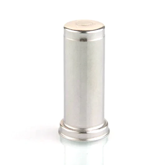
| Item | Brass Stepped Sensor Housing with Flared Base |
|---|---|
| Brand | AUNOV |
| Designing | Your 2D/3D files (PDF, DWG, STEP, IGS) are reviewed for manufacturability before any price is confirmed. |
| Tooling | Dies, fixtures and gauges are made in our own toolroom, so the die charge appears as its own quotation line, and ownership is confirmed on the quotation. |
| Samples | Samples are issued for approval before the run, so the sample is retained as the master, and later batches are gauged back to the signed sample. |
| Materials | Carbon steel (SPCC / DC01), 304 / 316 stainless steel, aluminium and brass are held on site; material substitutes are proposed only with your written approval. |
| Surface finish | Zinc, nickel or chrome plating, anodising, passivation or e-coat; the finish is inspected with the dimensional report on the first article. |
| Processing | Where the print calls for them, seats and threads are machined into the drawn shell; batch records on file mean repeat orders start from approved data. |
| Equipment | Deep drawing presses plus CNC turning centres for machined faces, with CNC turning centres for secondary operations and CMM inspection. |
| Tolerance | +/-0.01 mm on turned or milled features, +/-0.03 mm on formed details; dimensional reports accompany the first article. |
| Delivery terms | Delivery is quoted to your location: FOB, CIF or DDP, by sea or air as you prefer. |
Related Products


Frequently Asked Questions
Why does an engine bay change the design of this housing?
The engine bay is hot, vibrating and full of oil mist, salt and debris, so the housing is a mounting and thermal problem first and a pressure boundary second. An engine bay makes mounting and thermal control the primary design drivers, and its four jobs include holding pressure, carrying heat away from the element, surviving vibration without a fatigue crack, and keeping water out of the cable entry.
Why is the cable entry the real failure mode, not the seal?
Water and salt wick up the cable past a seal that would pass a bench test, and after winters of thermal cycling the elastomer’s compression set grows. The answer is a barrier design where the housing seals onto a connector or moulded boot and the cable jacket stays outside that seal entirely.
Why is the mounting face flat and square to the thread?
The same face is the seal and the thermal couple, so a sensor that does not sit square is neither sealed nor thermally coupled correctly. Its flatness and perpendicularity to the thread are measured as two values, and a square seat matters for both sealing and thermal coupling, which makes the mounting face the tightest dimension on the housing.
Is the reading meant to be the oil’s temperature or the port’s?
That single question changes the mounting geometry, the wall and the material: if it is the oil, the element is thermally isolated from the engine; if it is the port, the mount can be a solid thermal path and the housing simpler. The oil or port question decides the mounting geometry and the material, and it is worth answering before the drawing is complete.
Request a Quote for This Part
Send a drawing or sketch — get material advice, tooling cost and a per-piece price within 24 hours (working days).