
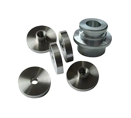
A machined compression connector is the part that comes when a compression tube system has to connect to something that is not a compression tube system – a port, a hose, a valve, a manifold, another material. And because it is a conversion part, it has the properties of both sides plus the problems that only exist at the boundary between them.
The compression side’s requirements are covered on the compression fitting page and they apply here unchanged. What this page is about is the boundary, and the specific failures that happen at a boundary even when both sides are individually correct.
What makes this part different from a straight compression fitting
- It has two independent interfaces and each one has its own tolerance scheme. A straight compression fitting has one interface and its tolerances are all about the ferrule and the tube. This part has a ferrule interface and a second interface of a completely different kind, and the two sets of requirements do not interact – except in three places, which are the interesting part of this page.
- It is a junction between materials more often than a straight fitting is, because the second interface is frequently in a different material system from the compression nut. That makes the galvanic question concentrated here rather than distributed.
- Its bore has a step in it. The compression side’s bore is set by the ferrule and is smaller than the tube’s bore, while the second side’s bore is whatever the system it connects to requires. So there is a step, and the step’s location and direction matter.
Where the two sides interact, and there are only three places
- Concentricity between the two sides. This is the tolerance unique to this part and no single interface’s tolerance implies it. A connector whose compression side’s axis and whose thread or port side’s axis are not coaxial will not seat correctly on either end. On a small part this is a real measurement and it is the one most often left out of an inspection plan, because nobody has written it down as a requirement.
- The bore step, and where it sits. If the second side’s bore is smaller than the compression side’s, the connector restricts the flow at the transition and the restriction is invisible in the part’s number. If the second side’s bore is larger – which happens when connecting to a larger system – then the connector expands the flow, which is unusual and has consequences for velocity and for the assembly’s pressure-drop calculation. Either way the bore on each side and the step between them should be stated as a positive requirement.
- The assembly torque reaching both sides. If the second interface is a compression connection rather than a thread, then tightening one side affects the other, and the order of assembly and the torques matter. This is a specific and frequently-missed requirement on a converter between two compression systems.
The compression side, and what it needs from the tube
Carried over from the compression fitting page but worth stating for this part, because the second side’s bore choice can conflict with the tube’s requirements.
- The tube’s outside diameter, wall thickness and tolerance, and its material. The connector is specified with a tube, not with a size, and the ferrule’s design assumes a wall thickness range.
- The ferrule’s geometry and the body’s seat, held to the ferrule fitting’s own requirements, because the ferrule and this body’s seat are a matched pair.
- Whether the tube must remain undistorted after assembly. This is the case where the connector should be a mechanical-compression or push-fit design rather than a ferrule design, and it arises when the tube is a capillary, an instrument’s tube, or something that depends on its cross-section.
- Whether the connection will be made once or repeatedly. This decides the connector type, exactly as it does on a straight compression fitting.
The second side, and its own requirements
Whichever it is – a pipe thread, a tapered thread, a port, a hose, a weld – it has its own seal method and its own requirements.
- A thread seals by interference or by a bonded seal or an O-ring, and the choice determines the tolerance range on the assembly torque. A taper needs a controlled torque and will relax with thermal cycling; an elastomer-sealed thread is far more forgiving.
- A face seal needs a flat face with a stated flatness and a stated finish, and the face has to be perpendicular to the axis, and a face seal on a converter is a real and frequently-missed feature.
- A weld end on a stainless steel connector is common and it has a specific consequence: the weld’s heat-affected zone, and therefore the grade’s L-status, because ordinary 316 risks sensitisation there and a sensitised weld on a pressure or wetted part is a corrosion initiation site.
- A hose end brings its own requirement, which is covered on the hose barb page – and the specific interaction here is that the barb’s diameter and its direction relative to the compression side determine whether the assembly can be made in a confined space.
Material, and this part concentrates the galvanic question
Standard stock: carbon steel, 304 and 316 stainless steel, aluminium and brass, with grade and temper confirmed in writing before tooling. Four specific points on this part.
- A converter is by definition where two materials meet. A stainless steel compression connector on a brass port, an aluminium body with a stainless steel compression nut, a carbon steel body with a stainless steel tube – each of these is a couple and each is in a connection that will probably be wet.
- Where the coupling cannot be avoided, the mitigation is usually on the converter. A plated carbon steel converter with a stainless steel nut, or a passivated stainless steel converter with a brass mating part, breaks the circuit. And on this part the plating’s thickness is a dimensional factor at the thread, so the masking and the allowance are part of the design rather than a finishing detail.
- 316L is the normal answer for a wetted stainless steel connector, and 304 is acceptable where the fluid is clean and non-chloride. The L grade where there is welding.
- Where the two sides are at genuinely different temperatures – which is more plausible on a converter than on a straight fitting, because the converter may sit at a thermal boundary – the expansion mismatch across the part becomes a load on the connections at both ends. This is worth checking on a part that converts between a hot line and a cold one.
Every masked area on this converter is a decision, not a detail
Finish selected from the drawing – plating, coating, anodising or passivation – with the finish inspected with the dimensional report on the first article. Four items, each of which is a masking decision.
- The ferrule seat, unmasked. This is the same requirement as on a compression fitting and it is the one that causes leaks when it is missed.
- The second side’s sealing face or thread, masked or specified post-finish with an allowance.
- On stainless steel, passivation is the answer and plating is not, for the same reasons as elsewhere on this site.
- Where the part is anodised – and an aluminium converter can be – the ferrule seat and the thread must be masked, and the anodising on a converter’s external surfaces is a cosmetic decision that costs nothing to specify correctly.
A converter is flagged per interface, plus the one dimension unique to it
+/-0.02 mm general machining, tighter on flagged dimensions, dimensional reports accompanying the first article. On a converter the flagged dimensions are per interface plus the one that is unique to this part.
- The compression side’s ferrule seat and geometry, to the ferrule fitting’s own tolerances.
- The second side’s thread or face, to its own requirements, gauged or measured as appropriate.
- Concentricity between the two sides. This is the tolerance that exists only on a converter and it is the one most often omitted.
- The bore on each side and the step between them, as a positive statement.
- Length and the wrench flats as a fit to the wrench, with the corner condition.
- General dimensions at a general band.
Both sides can pass and the combination still leak, so test the pair
- Both interfaces tested separately and together – the compression side against a representative fitting and tube, the second side against a representative mating part, and the assembled combination leak-tested. On a converter this is the only inspection that tests the whole part, because the part’s value is in the conversion.
- Concentricity between the two sides, measured on the CMM.
- Thread gauging on whichever interface is threaded, and the sealing face’s flatness and perpendicularity if it is a face seal.
- The ferrule seating verified against a standard, the same check as on a compression fitting.
- CMM data on the flagged dimensions with the report on the first article, and batch records filed so a repeat order starts from approved data – which on a converter matters because a repeat order has to reproduce a specific conversion of a specific standard.
- Finishing thickness and adhesion on the first article, with the masked areas verified.
What is on the other side of this connector
What is on the other side of this connector – specifically, does it already exist in the assembly, or is it also being specified? Because the most valuable outcome of a converter’s enquiry is frequently the discovery that the converter is unnecessary. Compression fittings and compression connectors have standardised end types, so a system that connects a compression nut to a port can very often be built with a compression fitting whose far end is already the right type, without any converter at all. The reasons converters get introduced are usually practical ones – a supplier’s standard does not include the size combination, or a material is wrong, or the assembly has to connect two things that were specified by different people who did not know about each other’s system. Those are all worth knowing, but they are worth establishing explicitly rather than assuming the converter is necessary. And if the converter is genuinely needed, the second question is whether the assembly could be made integral instead – a single machined body with a compression nut on one end and a thread on the other, with no additional joint at all – which removes a leak path and is very often achievable where a converter and a fitting are being used in sequence. Two questions at enquiry, both of which sometimes delete a part from the design.
You will find this part in our CNC Machining Parts range. Process notes, common materials and inspection points for every product in the family are collected across the cnc machining parts pages.
Specifications
| Item | Stainless Steel Discs, Washers and Stepped Flanges |
|---|---|
| Brand | AUNOV |
| Designing | Your drawing sets the part – samples are reverse-measured into a controlled drawing; revisions are re-quoted once rather than silently absorbed. |
| Tooling | Tooling is built and held under your part number, so tooling lead time stays under our control, and ownership is confirmed on the quotation. |
| Samples | First-article samples ship with a dimensional report and material certificate, so any deviation is corrected at sample stage, and mass production is gated on that approval. |
| Materials | Standard stock: carbon steel (SPCC / DC01), 304 / 316 stainless steel, aluminium, brass; grade and temper are confirmed in writing before tooling. |
| Surface finish | Finish selected from the drawing: plating, coating, anodising or passivation; the finish is inspected with the dimensional report on the first article. |
| Processing | CNC turning from bar or billet, concentricity held across operations; batch records are filed so a repeat order starts from approved data. |
| Equipment | Bar-fed CNC turning centres plus 3- and 4-axis machining centres; first articles and batch samples are checked on the CMM. |
| Tolerance | +/-0.02 mm general machining, tighter on flagged dimensions; dimensional reports accompany the first article. |
| Delivery terms | FOB, with DDP offered for EU and US addresses, payment by T/T or L/C, quoted in USD or EUR; repeat orders reuse the approved first article. |
Related Products


Request a Quote for This Part
Send a drawing or sketch — get material advice, tooling cost and a per-piece price within 24 hours (working days).