
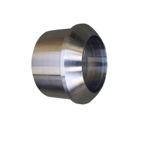
A finned heat-sink fitting is a fluid connector that is also a heat exchanger, and it fails in a way that a plain fitting never does: it is designed to be between two temperatures on purpose, and its whole job is to move heat from the hot fluid into the air. That means its requirements include a thermal design, and that thermal design interacts with its mechanical and its dimensional requirements in ways that are easy to miss.
The fins are the visible part and they are the least important. What matters is the base – the metal between the fluid and the air – and on this part that is a short, thick section of metal whose only purpose is to be a thermal bridge.
The base, which is the whole thermal design
Heat has to get from the fluid, through the fitting’s wall, into the fins. Four resistances in series, and the one the design controls is usually not the biggest.
- The fluid-side convection. For a gas or air inside the fitting, this is where the heat starts, and if the flow is laminar and slow it can dominate.
- Conduction through the base’s wall. This is the part the material and the thickness decide, and it is the resistance the fitting’s material choice actually governs.
- The interface between the base and the fins, if the fins are not integral. This is the one that is most often the bottleneck on a machined part, and the reason is the same one that appears everywhere else on this site: any coating, any interface material, and any anodised layer is an insulator sitting exactly where the heat has to move.
- Convection from the fin surfaces to the ambient air, which is the largest resistance on the whole path and is the reason fins exist at all.
So the honest statement about this part is: the fins improve the last resistance and nothing else. Adding fins to a fitting whose interface resistance is already dominant will give a disappointing result, and this is the single most common mistake with finned fittings. If the base-to-fin interface is not a solid metal-to-metal connection, the fins are largely decorative.
Fins, and the geometry rules that are not obvious
Fins are a well-understood subject and most of it is design practice rather than manufacturing, but three rules are worth stating because they are frequently violated.
- Fin spacing must exceed the boundary layer. A finned surface works because air flowing past it has a boundary layer that grows with distance from the surface. If the fins are closer together than the boundary layer is thick, the air between them is already stagnant when it arrives at the next fin, and that air is heated but not moving – so it carries no heat away. The result is that closely spaced fins can dissipate less than no fins. This is the single most important fin rule and it is the one most often got wrong.
- Fin thickness versus spacing. Fin thickness is normally set by what can be made rather than by what transfers heat, and this is one of the few cases where the material is the limit rather than the tooling. On a machined aluminium fitting the fin thickness will be whatever the smallest stable cutting tool can produce.
- Fin length and the tip. A longer fin dissipates more only up to the point where the fin’s own conduction from its base cannot supply the heat, and beyond that the tip is dead weight. And the fin’s tip condition matters: a rounded or a chamfered tip is a small thermal boundary condition effect that is well worth doing and costs nothing.
The fluid path, which is where the design has to be disciplined
A heat-sink fitting is in a fluid line, so it has the same flow and pressure requirements as any other fitting, plus the specific problem that a heat sink’s flow area is often restricted by the fin base’s diameter.
- The finned section’s bore must not be smaller than the line’s bore. A fitting that narrows the bore to accommodate the fins will either restrict the flow or accelerate it and change the pressure drop. Where the fins must stop short of the bore, the design has to allow the flow to pass around them – and that creates a velocity increase and a turbulence generation that affects both the pressure drop and the heat transfer.
- The pressure drop through the fitting is a specification. A heat-sink fitting is inserted into a line, and the line’s designer needs to know what it costs in pressure. This should be stated as a requirement with a stated fluid and a stated flow, and it should be measured rather than estimated.
- The internal surface finish, which affects the pressure drop and, on a condensing service, the condensate. On a fitting that will carry steam or a hot vapour, the internal surface matters.
- Where the fitting will be in a vapour service, and it will be if it is being used as an evaporator or a condenser or a hot-gas discharge, the design has to allow the condensate to drain. Liquid trapped in the bottom of a hot fitting is a thermal problem as well as a fluid one.
Material, and this is where the heat design is actually made
Carbon steel, 304 and 316 stainless steel, aluminium and brass, with substitutions proposed only in writing. On this part the material choice is the primary thermal decision, and it is worth being quantitative about why.
- Aluminium is the right answer and it is not close. Aluminium’s thermal conductivity is roughly twenty times that of stainless steel, and on a part whose purpose is to conduct heat, that difference is the whole design. A stainless steel heat-sink fitting is a heat sink with a major restriction in series, and it is a legitimate answer only where the fluid is corrosive enough that aluminium cannot be used.
- Why stainless steel sometimes appears: where the fluid is a corrosive process stream, where the fitting is in a high-temperature service where aluminium would lose strength, where it is a hygienic or a food application with a cleaning regime, or where the fitting must survive a pressure that aluminium would not. In those cases the fins are doing less work than the same fins in aluminium would, and the design has to account for it.
- Brass has good conductivity – about six times better than stainless steel and roughly a quarter of aluminium’s – and it is a workable answer where the fluid is water and the application is moderate. It is also the right answer where a galvanic compatibility requirement exists with brass fittings.
- Carbon steel conducts about five times better than stainless steel, which is often overlooked, so a steel heat-sink fitting is not as thermally hopeless as a stainless steel one. It is a legitimate answer where the fluid would corrode aluminium.
Surface finish, and where it destroys the part’s purpose
Zinc, nickel or chrome plating, anodising, passivation or e-coat, with the finish inspected with the dimensional report on the first article. On this part the finish question is much more important than on other fittings, and there is one rule that overrides everything else.
- Never anodise or plate the path from the fluid to the fins. The oxide layer on aluminium is a good insulator – that is the same property discussed on the enclosure and framework pages, and here it is fatal. An anodised finned fitting is substantially worse than a bare one, and it will look better while performing worse. If an anodise is wanted for appearance or for a wear surface, the fins’ surfaces and the fluid-path surfaces should be masked.
- A hard anodise on the fins is a specific mistake – it makes the fins look better and it adds an insulating layer to each one, and it thickens the fins so the spacing changes.
- Plating on aluminium is metallisation and it is a specialist process; where it is needed for a wear or a contact surface it should be specified with its own adhesion test.
- A conversion coating or a passivation on aluminium is a thin layer and a much lesser problem than an anodise, but it is still a layer and it should be evaluated rather than assumed.
- On the fins’ edges and tips, a coating changes the fin’s edge geometry and its emissivity, so a bright emissivity becomes a lower one and the radiation component of the heat transfer drops. On a part with a lot of radiation – a hot, exposed fitting – this is measurable.
Tolerance, and where precision actually helps here
+/-0.01 mm on turned and milled features, capability checked on the first article. On this part the flagged dimensions are the fluid path and the fit, and the fins are generally not precision features.
- The bore’s diameter and its concentricity to the external thread and spigot, since a non-concentric bore on a fitting that also has a spigot will not seal evenly and will restrict flow unevenly.
- The bore’s diameter in the finned section, where it is the flow restriction and therefore the pressure drop.
- Sealing faces, – flatness and perpendicularity – and threads, per their own requirements.
- Fin spacing and fin thickness, not as tolerances for their own sake but because fin spacing is the boundary layer condition and a generous tolerance on it is a tolerance on the part’s effectiveness. It is worth specifying these as a functional group.
- Fin length, where it affects the base-to-fin conduction and therefore the fin’s effectiveness.
- General dimensions at a general band.
Pressure drop at a stated flow is the number the customer’s design needs
- Pressure drop at a stated flow and fluid, on every part or a sample. This is the functional test and it is the number the customer’s design actually needs.
- Thermal performance, if it is a requirement – a temperature drop across the fitting at a stated flow, or a specific outlet temperature. Where the part is being bought for its thermal performance, testing it thermally is worth more than any dimensional report.
- Fin spacing, thickness and length, verified on the first article and periodically.
- Bore diameters and concentricity, and threads and sealing faces as normal.
- Finishing thickness and adhesion, with the masked areas – which on this part should include the fins and the fluid path – verified.
- Burr and edge condition on the fins, verified. On a finned part the fin edges are the most common place for a burr, and a burr on a fin edge is both a handling hazard and a thermal disruption, because it disturbs the boundary layer at exactly the point where the boundary layer matters.
The temperature drop needed, at what flow
What is the actual temperature drop you need across this fitting, at what flow rate, and with what fluid? Because that number, with the fluid, decides everything on the page. If the requirement is a modest temperature drop in a water line, an aluminium fitting with modest fins will do it and the fin spacing barely matters. If the requirement is a substantial drop in a hot gas, then the fin spacing has to be designed against the boundary layer, the base has to be as short as possible, the surface has to be bare rather than anodised, and the fins have to be as long as the convection coefficient justifies. And if the fluid turns out to be something aluminium cannot see – a strong alkali, a strong acid, a food product with a cleaning regime – then the material is stainless steel, and the whole thermal design has to be reworked around a conductivity that is twenty times worse, which usually means a different approach to the problem entirely rather than better fins. Four numbers on the enquiry: fluid, flow, inlet temperature, required outlet. It is the difference between a fitting and a designed heat exchanger.
This part sits inside our CNC Machining Parts range. Across the cnc machining parts pages you will find the process notes, common materials and inspection points behind every product in the family.
Specifications
| Item | Finned Aluminum CNC Machined Heat Sink Fitting |
|---|---|
| Brand | AUNOV |
| Designing | Made to your 2D/3D drawings (PDF, DWG, STEP, IGS) – unusual walls, threads or tolerances are feasibility-checked first; revisions are re-quoted once rather than silently absorbed. |
| Tooling | Dies, fixtures and gauges are made in our own toolroom, so a die can be re-cut against the approved drawing, and the charge is refundable against agreed volumes. |
| Samples | Samples are produced on the production tooling, so what you approve is what you get. |
| Materials | Carbon steel (SPCC / DC01), 304 / 316 stainless steel, aluminium and brass are held on site; material substitutes are proposed only with your written approval. |
| Surface finish | Zinc, nickel or chrome plating, anodising, passivation or e-coat; the finish is inspected with the dimensional report on the first article. |
| Processing | CNC turning with milling and drilling in as few setups as the geometry allows; every stage is logged against your part number. |
| Equipment | CNC turning centres with bar feeders and 3-/4-axis machining centres, with CNC turning centres for secondary operations and CMM inspection. |
| Tolerance | +/-0.01 mm on turned and milled features; capability is checked on the first article before the run continues. |
| Delivery terms | FOB, with DDP offered for EU and US addresses, payment by T/T or L/C, quoted in USD or EUR; price breaks tie to annual volume. |
Related Products


Request a Quote for This Part
Send a drawing or sketch — get material advice, tooling cost and a per-piece price within 24 hours (working days).