
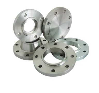
A flange ring with bolt holes is the most ordinary part in this catalogue, and it has one job that is almost never stated on the drawing: to transfer load from a rotating or stationary body into a structure, through a bolt circle, without the bolts being the weakest thing in the joint.
Which is why the interesting dimension on this part is almost never the diameter. It is the relationship between the bolt circle, the ring’s thickness, and the material – because a bolt circle is a lever arm, and everything about how this part behaves follows from how long that arm is.
The joint, and where the load actually goes
A ring bolted to something carries load in three distinct ways, and each one has its own failure mode.
- Axial load. Something pushes the ring’s face against the mating face, or pulls it away. This is carried directly by the bolt shanks in tension or compression, and by the ring’s face in bearing around each hole.
- Torque. Something tries to rotate the ring about its axis. This is resisted almost entirely by friction at the joint face, and friction is proportional to the bolt preload. So the torque capacity of the joint is a function of the bolt specification and the tightening method, not of the ring’s material.
- Bending moment. Something applies a force at a radius. This produces a couple that one side of the ring has to carry in tension and the other in compression, and this is the load case that sizes a flange.
Most flange failures are not tensile failures. They are the third case: a moment that opens a gap on one side, which relieves the bolt load on that side entirely, which increases the load on the bolt opposite, which is now the only load path. A joint that has opened on one side is a joint that has become a joint with half its bolts.
The lever arm, which is the design variable
The bending stress at the bolt circle from an applied moment depends on the radius at which the load is applied divided by the radius of the bolt circle. Making the ring larger – moving the bolt circle outward – reduces the stress at the bolt for the same applied load. This is why flange rings that must carry a moment are often noticeably larger than the bore they surround.
Three specific consequences on the drawing’s dimensions:
- Bolt circle diameter is a strength dimension, not a layout dimension. On a ring where the load is a moment, the bolt circle is the number that sizes the part.
- Radial distance from the bore to the bolt circle is what carries the bending stress in the ring’s own material. The ring will crack or yield at the root of the bore – at the section between the bore and the first bolt – and the thickness there is what resists it. This is the section that fails, and it is frequently the thinnest part of the design.
- Ring thickness, which resists shear between adjacent bolts and between the bolt and the edge. A thin ring with a large bolt circle will deform into an oval under load, and a deformed ring is a ring whose bolt holes no longer align.
Edge distance, which is a simple number that gets missed
The distance from a bolt hole to the edge of the ring is not decorative, and there are two limits on it.
- A minimum, for material. Too little material beyond the hole and the ring tears out under the bolt’s bearing load. The bearing stress at the hole is a straightforward calculation – the bolt’s preload divided by the ring’s thickness times the hole’s diameter – and the edge distance has to be large enough that the net section through the hole is still adequate.
- A maximum, for the bolt’s ability to seat. Too much edge distance and the ring flexes so much under the bolt that the bolt’s clamping is spread over a large area instead of being concentrated. A ring that is too compliant under load will lose preload over time as the metal relaxes into a new shape.
So the useful rule on this part is that edge distance is bounded from both sides, and a flange that has been designed by adding material where it seemed thin will often be at the wrong end of one of them.
Bolt hole type, which is a real decision
Three options, and they have different failure modes.
- Clearance holes with through bolts. The simplest and the most adjustable. The ring’s holes carry no bolt load other than shear, and the clamping force is applied through the ring’s face.
- Threaded holes with studs or screws. The ring is threaded. This makes the ring thicker and heavier, it makes the thread the weak element, and it means the ring cannot be assembled from one side.
- Counterbored or spotfaced holes for cap screws. This keeps the fastening head inside the ring’s profile so another component can sit against it. It introduces a counterbore – a second diameter and a depth, and a flat bottom whose depth has to leave enough material – and the counterbore’s flatness becomes a functional surface because the screw head will bear on it.
Where the ring is stainless steel, add the threading consideration: tapping stainless steel is a demanding operation and the thread’s strength is limited by the tap drill and by the material’s tendency to gall. On a stainless steel ring, a threaded hole is worth thinking about twice.
A flange ring forces strength, corrosion and appearance at once
Carbon steel, 304 and 316 stainless steel, aluminium and brass, with material substitutes proposed only in writing. On a flange ring the material decision is really three decisions at once.
- Strength, for the loads. Aluminium has a lower yield and a lower modulus than steel, so a ring carrying a moment will need either a larger section or a larger bolt circle. Brass is stronger than aluminium and much softer in the modulus sense.
- Corrosion, for the environment. 304 for general service, 316L for chloride-bearing, and the coupling question: an aluminium ring bolted with steel bolts is a galvanic couple at every bolt hole, and the crevice at the bolt hole is exactly where water collects. This is the classic case where the isolation between the ring and the fastener has to be designed rather than hoped for.
- Mass, if the assembly is weight-sensitive. On a rotating or a moving assembly, a steel ring’s mass is not just inertia – it also produces a bearing load and a centrifugal load, and on a high-speed ring the hoop stress from rotation can be a real design case.
On a rotating ring, add one requirement that is easy to miss: the material’s strength at the bolt holes after fatigue cycling. A ring that is bolted and unbolted repeatedly, or that is on a rotating shaft and sees cyclic bending, will fatigue. The fatigue initiation site will be at the bolt hole’s edge – which means the hole’s edge condition, its burr removal, and whether the hole was reamed rather than drilled all matter to the life. A drilled hole leaves a work-hardened and burred edge at exactly the location where fatigue initiates.
Flatness, and why it is not cosmetic
The ring’s face has three jobs, and flatness is the requirement that underpins all three.
- It is the clamping surface. A ring whose face is dished loads two or three bolts and leaves the rest carrying nothing. Then the loaded bolts creep, the preload drops, and the joint loosens. A flat face is a joint that stays tight.
- It may be a sealing surface. If anything is sealed between the ring and its mating face, that face’s flatness is a seal specification and the surface finish matters with it.
- It may be a register. If another component locates against the ring’s face, the flatness and the parallelism to the bore are what make it locate. A ring that is flat but not parallel to its bore will locate at one point and gap at another.
Two practical notes. First, a ring is often the part that gets sacrificed to make something else’s flatness, and on a machined ring it is often the part that distorts – a ring is a thin annular section and its flatness is sensitive to how it was held during its final facing operation. Second, flatness must be stated against a named surface or as an overall flatness, because “flat to 0.05” without that is not a specification.
Tolerance, and where the budget goes
+/-0.01 mm on critical bores, confirmed at the DFM stage, with finer bands confirmed from capability. On a flange ring the flagged dimensions are:
- Position of each bolt hole on the bolt circle, as a true position to the ring’s axis. This is the dimension that decides whether the ring will assemble, and it should be tighter than the hole’s size – a hole at the right size in the wrong place does not bolt on.
- Concentricity of the bore to the bolt circle, held independently. On a ring that locates something, this is what makes it locate.
- Runout of the mating face to the bore, rather than just flatness, because runout combines the two and it is the one that matters for a face used as a register.
- Flatness of the mating face against a named datum.
- Perpendicularity of the face to the bore axis where the ring bolts against something that is itself a datum.
- Any counterbore’s depth, flatness and concentricity, since the screw head bears on it.
- Overall dimensions, thickness, and outside diameter at a general band. On a ring these are structural but not dimensional, and holding them tightly is wasted money.
Plating a threaded hole changes the thread’s fit and its wear
Zinc, nickel or chrome plating, anodising, passivation or e-coat, with the finish inspected alongside the dimensional report on the first article. On a ring the finish has three specific consequences.
- Plating a threaded hole changes the thread’s fit, and it will flake at the thread’s roots. Threads should be masked or the plating specified post-thread with an allowance.
- Plating the mating face changes flatness very slightly, and more importantly it changes the friction coefficient at the joint – which, as noted, is what carries the torque. A plated face is a different friction condition and the joint’s torque capacity is different.
- Anodising applies only to aluminium and it closes the bolt holes, which on a clearance hole is beneficial and on a locating hole is not. And an anodised aluminium ring’s face is a thermal insulator, so an anodised ring cannot be a thermal path.
Inspection: CMM data on the bolt circle’s true position and on the concentricity of the bore to the circle, reported as actual coordinates or angular positions rather than as a general band; the mating face’s flatness and runout; a first article assembly check against the mating component, which on a ring is the most informative inspection available because it tests the whole tolerance stack at once; and where the ring is fatigue-sensitive, an edge-condition check on the bolt holes. Finishing thickness and adhesion on the first article, with masked areas verified.
A bolt pattern holding a cover, or a reacted moment
What load is this ring actually carrying – is it a bolt pattern holding a cover shut, or is it a moment being reacted through the bolt circle? Those two ring parts look identical and they are entirely different parts. A cover ring needs good flatness, a sensible bolt circle for assembly, and corrosion resistance. A moment-reacting ring needs a bolt circle sized against the applied moment, a section between the bore and the first bolt sized against the resulting bending stress, and probably more thickness than anyone first thought. There is also a third case worth separating: a ring whose bolt circle is used to set a runout – a rotating component where the ring locates a shaft and its dynamic balance matters more than its static strength. Establishing which of the three it is at enquiry stage costs one sentence, and it changes the bolt circle, the thickness, the tolerance priorities and, on a rotating part, the balance requirement.
This part belongs to our CNC Machining Parts range. The cnc machining parts pages collect the process notes, common materials and inspection points behind every product in the family.
Specifications
| Item | Stainless Steel Flange Rings with Bolt Holes, Five-Piece |
|---|---|
| Brand | AUNOV |
| Designing | Made to your 2D/3D drawings (PDF, DWG, STEP, IGS) – a manufacturability review comes back with the quotation; the approved drawing is kept as the controlled master. |
| Tooling | Die design and toolmaking stay in house, so die cost stays transparent, and first-article timing is measured from the tooling start date. |
| Samples | Sample approval is documented: dimensions, finish and material recorded for later comparison. |
| Materials | Standard stock: carbon steel (SPCC / DC01), 304 / 316 stainless steel, aluminium, brass; material substitutes are proposed only with your written approval. |
| Surface finish | Zinc, nickel or chrome plating, anodising, passivation or e-coat; the finish is inspected with the dimensional report on the first article. |
| Processing | Turning, milling and drilling sequenced to minimise handling and re-chucking; first articles verify the whole flow before the run is released. |
| Equipment | Turning centres fed from bar, with machining centres for milled features, with CNC turning centres for secondary operations and CMM inspection. |
| Tolerance | +/-0.01 mm on critical bores, confirms at DFM stage; finer bands confirmed from capability data before quoting. |
| Delivery terms | FOB, with DDP offered for EU and US addresses, payment by T/T, L/C at sight or D/P; repeat orders reuse the approved first article. |
Related Products


Request a Quote for This Part
Send a drawing or sketch — get material advice, tooling cost and a per-piece price within 24 hours (working days).