
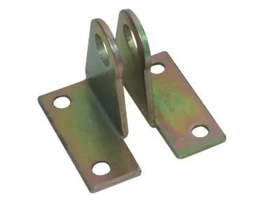
A bracket with two upright ears is a stamped part that has one specific job beyond mounting: it has to stop the thing it holds from rotating. Two ears at a spacing is the cheapest way to resist a torque that a single tab cannot resist, and the whole design is about turning a flat sheet into a bracket that carries load without twisting – and about the one place where a stamped bracket almost always fails.
On a die-stamped bracket with a general tolerance of +/-0.05 to +/-0.1 mm, most of the engineering is not dimensional. It is about the bend’s ability to take the load, and about which end of the part the material should crack at.
What two ears actually resist, and what they do not
A single-tab bracket resists load in one plane and offers very little resistance to twisting about the mounting axis. Two ears, spaced apart, resist the torque that a single tab would simply deflect through.
- The ears’ spacing is the design variable. Torque resistance scales directly with the spacing, so doubling the spacing roughly doubles the moment a pair of fasteners can resist before the ears deflect. This is the cheapest stiffness available on a stamped bracket and it costs nothing but envelope.
- The ears’ height is the second variable. The ear acts as a lever arm in bending, and its height resists the moment about the foot of the bracket. A shallow ear bends easily; a tall ear is proportionally much stronger. Again, this is often free space.
- What two ears do not do: they do not resist a load pulling the bracket off in an arbitrary direction, and they do not prevent the bracket’s foot from lifting. A bracket with two ears at the top and a single bolt at the foot is a good moment-resisting joint and a poor pull-out joint, and the drawing should make clear which it is.
The foot, and the failure that nearly always happens
On a bracket like this the ears are fine and the foot is the problem, for a reason that is structural rather than dimensional.
The bracket’s foot is a bend from the flat blank. The material at the bend has been work-hardened by the forming, and on the outside of the bend it has been stretched to its strain limit. Everything else on the bracket is in the flat condition and can flex; the bend cannot. So when the bracket is loaded, the entire load path funnels through the bend, and the bend is the weakest section by a wide margin.
Three consequences and three responses:
- The bend’s fatigue life is the bracket’s life. On a cyclically loaded bracket – a motor mount that starts and stops, a bracket carrying a vibrating machine – the failure will initiate at the bend on the tension side, regardless of how strong the rest is.
- The bend radius and the material’s bend allowance decide it. A tight bend on a low-carbon steel can crack on the outside during forming, and even where it does not, it leaves the section close to its limit before any load is applied.
- A relief at the bend does more than almost anything else available. A formed relief, a bend-relief slot, or an increase in the bracket’s width at the bend gives the material somewhere to go, and it is the standard fix. This is a geometry decision that costs nothing and it belongs in the drawing review rather than in the failure analysis.
So the question on this part is worth asking early: is this bracket cyclically loaded? A motor end bracket carrying a motor with a rotating imbalance is cyclically loaded whether or not the design acknowledges it, and that single fact determines whether the bend needs a relief and whether the foot needs to be gusseted.
The motor’s requirements, which are not the bracket’s
On a motor end bracket the mounting pattern is dictated by the motor and the pattern is usually the tightest thing on the drawing. Three things flow from that:
- The bolt pattern’s position tolerance is set by the motor, not by the bracket. A motor’s bolt circle and its register face are what the bracket must match, and the register – usually a pilot diameter or a spigot – is the bracket’s most important dimension because it is what locates the motor.
- The register’s fit decides whether the motor is aligned by the bracket or by its feet. If the register is a slip fit and the feet carry the motor, then the bracket’s function is only to prevent rotation and to provide a second mounting point, and the whole design changes accordingly.
- A motor’s bolt circle is usually toleranced as a set, not hole by hole. Stating the position tolerance as a true position on the bolt circle and stating the register’s concentricity to the bolt circle as a separate requirement is the honest way to write it.
Motor mount vibration, which is the bracket’s real job
A motor mount’s purpose is usually not to hold the motor’s weight. It is to hold the motor’s position against the forces the motor creates, and those forces are dynamic.
- Torque reaction. A motor that starts and stops produces a torque reaction about its axis. The two ears resist this and the foot resists the overturning moment. This is the design’s primary load case and it is a cyclic one, which brings back the bend.
- Cable and hose pull. A motor’s cables and hoses are stiff enough to apply real loads. A bracket that carries a cable’s pull will see a cyclic load at the cable entry, and the cable entry’s edge is a stress concentration where the cable bears on the sheet metal. This is a very common source of complaint and it is nearly always a design detail rather than a manufacturing defect.
- Imbalance vibration, if the motor’s rotor is unbalanced or if its load is, which produces a rotating force on the bracket. On a bracket with a large unsupported foot this shows up as a buzz and eventually as a fatigue crack at the bend.
- Sheet metal’s response. A stamped bracket is inherently flexible compared to a machined one, and that flexibility is sometimes the design’s best feature – it absorbs vibration instead of transmitting it. But it also means the deflection at the bolt holes is larger and the joint loosens. On a motor mount this is the tension between “stiff enough to stay tight” and “flexible enough to not transmit vibration”.
Material, temper and thickness
Carbon steel, 304 and 316 stainless steel, aluminium and brass are held on site, with mill certificates and heat numbers on the first article. On a stamped bracket the material decision comes down to four things, and the thickness is the one that gets under-specified.
- Thickness is a structural specification. A stamped bracket’s whole stiffness and its whole fatigue life come from the material gauge, and the gauge is the first thing on the drawing and the last thing anyone thinks about. Stating a gauge tolerance and a minimum is more important than any other tolerance on the part.
- Temper matters for stamping and it matters for the finished part. A low-carbon steel in a quarter or dead-metal temper forms well and has more ductility in service. A half or full hard temper is much stronger in the flat and much more likely to crack at a bend. On a bracket that has to form two bends, the temper is a forming requirement and it has to be chosen for that.
- Aluminium is a good choice where weight matters and it stamps well, with the caveat that its fatigue strength is low and it will not take a repeated load the way a mild steel will. On a cyclically loaded bracket, an aluminium bracket needs a shorter design life than a steel one of the same geometry.
- Stainless Steel for corrosion or for a hygiene application. It work-hardens severely in forming, so its bend radius needs to be generous and its tooling wear is high. Where the bracket is in a wet or chloride environment, stainless steel is the right choice and the forming difficulty is the price.
Zinc plating, and the dimensional consequence
Zinc, nickel or chrome plating, anodising, passivation or e-coat, with the agreed finish travelling with the part number. On a stamped bracket, plating has four consequences, and the one that causes most returns is the first.
- Plating closes the holes and changes the ears’ thickness. On a bracket whose holes locate the motor, a plating that closes the clearance hole changes the fastener’s fit. The bolt holes should be masked, or the plating specified post-plate with an allowance, or the clearance hole sized for the finished condition.
- The register diameter changes. If the register is a slip fit and it is plated, the plating closes it by roughly twice its thickness on the diameter. A plated register on a slip-fit assembly will not slip.
- Plating on a work-hardened bend is a cracking risk. The bend’s outside surface is already at high strain, and a brittle coating on a strained surface can crack. This is a reason to mask the bend region on a heavily formed bracket, which also protects the fatigue-critical area.
- Plating changes the friction at the joint. On a bracket that resists torque through friction at the foot – and most stamped brackets do, because the sheet is thin and flexible – the friction coefficient is a design variable and a plated surface is a different friction condition from a bare one.
Where the bracket is bare and painted or powder-coated, the same masking logic applies, plus the point that a powder coat’s thickness is a meaningful fraction of a thin sheet’s bend allowance.
A stamped bracket’s register position matters more than its outline
+/-0.05 mm to +/-0.1 mm across the part, with critical dimensions carrying CMM data. On a stamped bracket the flagged dimensions should be specific and they are not the outline.
- The register’s diameter and its position to the bolt circle, held tightly. This is the bracket’s most important dimension and it is the one that decides whether the motor mounts square.
- The bolt circle’s true position to the register, as a set.
- The ears’ spacing, held more tightly than the general tolerance, because the ears’ spacing is what carries the torque reaction and a bracket whose ears are out of spacing will not fit.
- Flatness of the mounting face, because the bracket’s foot must sit flat for the joint to work and a dished sheet-metal foot will rock on the mounting surface.
- The ears’ flatness and their mutual parallelism – a bracket with two ears that are not parallel will not accept two bolts.
- Bend angles and their position held, but with the understanding that these are the dimensions that will vary with the material lot. On a stamped part, the honest allocation is to hold the flat-pattern features and the bends to a general tolerance, and to spend the effort on the features that are machined or that locate.
- Thickness, as a minimum, on the structural sections.
- The outline, at the general tolerance, unless it locates something.
Bend angles drift with the coil lot, not with the tool
- Bend-angle verification on a sample, against the material’s expected springback. On a stamped bracket the bend angles are the dimensions that drift with the coil lot, and a first article from one lot does not prove the next one.
- CMM data on the flagged dimensions – the register, the bolt circle, the ear spacing, the flatness – with the data accompanying the shipment.
- Burr and edge condition on the outline, the holes and the ears. On a stamped part the edge condition is a separate inspection item because it is not dimensional and it is a common source of assembly complaints and handling injuries.
- Plating thickness and adhesion on the first article, with the masked holes and register verified.
- A functional fit check against the motor or against a master, on a sample. On a bracket this is the most informative inspection available and it tests the register, the bolt circle and the flatness together.
- Flatness check under the stated loading – often a specific check that the bracket’s foot does not rock.
Holding a motor’s weight, or resisting its torque reaction
Is this bracket’s job to hold the motor’s weight, or to hold the motor’s position against a torque reaction while the machine starts and stops? Those are different brackets. A weight-holding bracket is a simple stiff plate with a hole pattern and almost no design content. A torque-reacting bracket is a fatigue part, and its life is set by the bend at its foot, which means it needs a bend relief, a temper chosen for forming, and possibly a gusset – three changes that cost almost nothing and that are almost never specified on the original drawing. This is also the part of the drawing that most often gets revised after the first field failure rather than before the first article. Asking it at enquiry stage costs one sentence and it turns a bracket from an off-the-shelf stamping into an engineered one.
Custom Metal Stamping Parts is the parent range for parts like this one; the overview page gathers the tooling logic, finishing options and tolerance notes that apply across the family.
Where this part is used
A bracket with two upright ears does one specific job beyond mounting: it stops the thing it holds from rotating. Two ears at a spacing resist a torque that a single tab simply deflects through, and the whole design is about turning a flat sheet into a bracket that carries load without twisting. You will find this shape wherever a motor, a gearbox or an actuator has to be restrained against a torque reaction – the drive shaft tries to turn the housing, and the ears are what refuse it.
The pattern shows up on motor end brackets, on actuator mounts, and on the fixtures that hold a subassembly while a torque reaction is applied. The reason the ears work is cheap is that they use envelope space that would otherwise be empty. The reason they fail is also cheap: they handle the moment well and the pull-out badly, and most reported failures are at the foot rather than at the ears.
What we need to quote it
Send the ear spacing, the ear height and the material grade and thickness, and tell us the torque the bracket has to react and whether it is static or cyclic. The ear spacing is the design variable – torque resistance scales directly with it – so a drawing that leaves it as a note will come back with a question. Also tell us the fastener size and whether the foot is bolted at one point or two, because that is what decides whether the joint resists pull-out as well as moment.
Specifications
| Item | Aluminum CNC Machined Motor End Bracket |
|---|---|
| Brand | AUNOV |
| Designing | Drawings are reviewed for feasibility, and the agreed version is what production runs against. |
| Tooling | Die design and toolmaking stay in house, so die cost stays transparent, and ownership is confirmed on the quotation. |
| Samples | First-article samples ship with a dimensional report and material certificate, so any deviation is corrected at sample stage, and the signed sample is kept for future reorders. |
| Materials | Carbon steel (SPCC / DC01), 304 / 316 stainless steel, aluminium and brass are held on site; mill certificates and heat numbers accompany the first article. |
| Surface finish | Zinc, nickel or chrome plating, anodising, passivation or e-coat; the agreed finish travels with the part number. |
| Processing | Die stamping with in-press forming and piercing; every stage is logged against your part number. |
| Equipment | Mechanical presses 5-250 T with progressive dies, with in-house toolmaking to keep dies and fixtures maintained. |
| Tolerance | +/-0.05 mm to +/-0.1 mm across the part; critical dimensions carry CMM data with the shipment. |
| Delivery terms | Shipping terms are set with the order: FOB, CIF or DDP, T/T or L/C, door delivery quoted. |
Related Products


Request a Quote for This Part
Send a drawing or sketch — get material advice, tooling cost and a per-piece price within 24 hours (working days).