
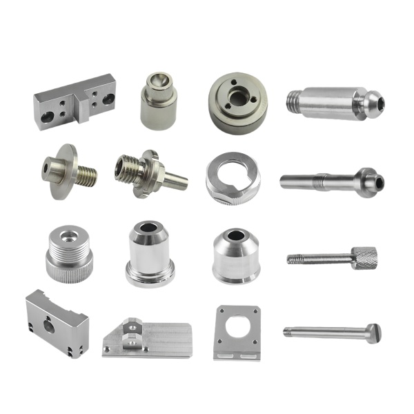
The Assorted Aluminum CNC Machined Fittings Nozzles and Blocks family concentrates the hardest inspection problems in the shop into the smallest volumes: parts whose function lives inside bores a few millimetres across, where the flow area, the intersection condition and the internal finish cannot be seen and must therefore be measured, inferred or verified by other means. This page covers how orifice tolerance converts directly into flow variation, what cross-drilled blocks demand at the intersections, how O-ring glands and internal threads are held in one-piece bodies, where anodizing fails to reach, and what we verify before a nozzle or block ships.
The orifice sets the flow, and its tolerance is the customer’s process variable
Flow through a small orifice scales roughly with the fourth power of diameter, which makes the bore the single most leverage-rich dimension on the part: a 3% diameter error produces about a 12% flow error. On a nozzle whose bore is 1.5 mm, a +/-0.02 mm tolerance band – comfortable by general machining standards – swings flow by roughly +/-5% before surface finish and edge condition contribute their own share. The decision the drawing has to make is whether the part is a fitting that happens to have a hole, or a flow device that happens to be machined, because the two get very different treatment.
- We hold nozzle bores by boring rather than by interpolating where diameter accuracy matters most, because a boring bar’s single-point path is more controllable than a circular interpolation whose radius errors land directly on the bore diameter.
- Reaming buys roundness and finish economically on straight through-bores in aluminium, and we size the reamer to the tolerance’s target, not its midpoint, once the measured drift of the process is known.
- Where the print specifies flow rather than diameter, we propose the equivalent diameter band and a verification method at quotation, because a flow spec is testable and a diameter spec alone is not.
- Entry edge condition is called out explicitly: a chamfered or burred orifice entry changes flow coefficient noticeably, and burrs here survive a dimensional inspection entirely.
Cross-drilled blocks fail at the intersections nobody can see
A machined block with intersecting internal passages – a manifold or nozzle body – has its real quality concentrated at the points where two drilled holes cross. At each intersection the drills break through into open space, the tool deflects, and the result is a burr at the crossing that no one can see and no standard gauge can find. That burr then detaches in service, lodging in a valve or an orifice downstream, or it partially blocks the intersection and skews the passage’s flow split from the first day.
How we control intersections on blocks:
- Passage layout is reviewed at quotation for drill access and intersection angle – crossings as close to perpendicular as the layout allows cut cleaner than grazing intersections, and a grazing crossing is a burr generator by geometry.
- Drilling sequences are ordered so the through-hole is completed before features that would trap chips, and peck cycles are set to clear swarf from deep crossings.
- Intersection deburr is a specified operation: brushes, back-chamfer tools or abrasive flow depending on access, with the method written in the control plan per passage diameter.
- Plugged or capped passage ends get the plug seated against the print’s pressure and sealing requirement – a thread seal or a pressed plug is a pressure decision, not a style choice.
- Cleanliness is verified, because on a finished block the chips that matter are the ones already inside: we flush and inspect by a stated method, and the block ships capped.
O-ring glands and internal threads decide the seal in a one-piece body
Aluminium nozzle and block bodies seal in three typical ways: a face O-ring, a radial O-ring in a groove, and a threaded connection with a gasket or crush element. All three put the seal geometry in the same machined setup as the flow geometry, which is the design’s strength and the machining’s burden – a body whose gland is eccentric to its bore leaks on one side while measuring perfect on the other.
- Gland diameter, width and surface finish are held as a set: an O-ring groove with a finish above about Ra 1.6 abrades the ring on every pressure cycle, and a groove too shallow by 0.05 mm over-compresses it and splits it at the first pressure spike.
- Radial glands are machined concentric to the bore in the same setup, and the concentricity is a checked dimension on the first article rather than an assumed consequence.
- Internal threads in a one-piece body get their torque-ability verified with the mating part where possible – the thread must bottom the sealing face before it bottoms itself, and that relationship only shows under assembly.
- Where the customer supplies the mating half, we ask for its gauge state at drawing review, because a seal system is two parts and we only machine one of them.
Anodizing cannot reach where current cannot reach
Many parts in this family are anodized for corrosion resistance and appearance, and anodizing is an electrochemical process whose coverage inside small deep bores is limited by throwing power – the ability of current to reach down a passage whose mouth is small relative to its depth. A 1.5 mm bore 20 mm deep anodizes fully at the mouth and thinly or not at all at the bottom, and the transition zone is invisible from outside. The consequences are localized: an unprotected bore in a part that otherwise looks finished will corrode exactly where the fluid runs.
- We raise bore depth-to-diameter ratios at quotation whenever anodizing is on the print, and where coverage cannot be guaranteed we propose alternatives – chromate conversion coating, which is chemical rather than electrochemical and reaches internal surfaces that anodizing cannot, or a material change.
- Critical bores in anodized nozzles are frequently machined after coating, restoring both size and bare-metal condition deliberately, and the sequence is stated in the process plan.
- Where internal corrosion protection is a functional requirement rather than a cosmetic one, the verification method is agreed in advance, because an eddy-current probe that fits a 1.5 mm bore is not standard equipment.
- Threads and sealing lands follow the same masking rules as on any anodized machined part: film on thread flanks is an interference and a debris source, so they are masked, re-cut or oversize-tapped by plan.
How we verify internal geometry on nozzles and blocks
Verification for this family leans on methods that see inside, and every release ships with the evidence:
- Bore diameters at defined stations by pin gauge, bore gauge or optical means scaled to the passage size, reported as values so taper and barrel appear as data rather than surprises.
- Orifice edge condition inspected at magnification on the first article and sampled in production, because the entry chamfer and burr state are flow features the gauge misses.
- Intersection deburr verification by the agreed method – optical, borescope or flow check – on the sampling plan, with the method named in the control plan.
- Gland and seal geometry measured as a set on the first article, including concentricity of radial glands to the bore, plus an assembly trial against the mating part or gauge where one exists.
- Cleanliness and capping verified at packing: flushed per the stated method, passages capped, and the cap condition itself checked, because an uncapped block collects the shop’s air between here and the customer.
- Coating coverage records where anodizing or conversion coating runs: film or coating class, and the internal-surfaces arrangement – masked, re-machined or chemically converted – stated on the release.
Material certificates per heat and the first-article archive travel under the part numbers as on every machined family, so a repeat nozzle or block order inherits the verified internal geometry rather than a fresh interpretation of it.
You will find this part in our CNC Machining Parts range. Process notes, common materials and inspection points for every product in the family are collected across the cnc machining parts pages.
Specifications
| Item | Assorted Aluminum CNC Machined Fittings Nozzles and Blocks |
|---|---|
| Brand | AUNOV |
| Designing | Send us your 2D drawing, or mail a fitting sample for measurement, DFM feedback is returned with the quote. |
| Tooling | Dies engineered and produced in our own toolroom, stored under your part number. |
| Samples | First-article samples of the fitting ship with a dimensional report plus material certs. |
| Materials | Stock for this part leads with aluminium, alongside carbon steel (SPCC / DC01), 304 / 316 stainless steel, brass and copper, per the drawing. |
| Surface finish | Finish options: plating, e-coat, powder coating, anodising or passivation, fixed at the drawing review. |
| Processing | Progressive deep draw stages with in-line annealing as the draw ratio demands, then pierced and machined in house. |
| Equipment | Mechanical presses 5-250 T and hydraulic presses 250-500 T, CNC turning centres, plus a climate-controlled CMM room. |
| Tolerance | +/-0.1 mm on as-drawn features, +/-0.03 mm on machined surfaces. |
| Delivery terms | Standard terms FOB, DDP offered to EU and US, T/T and L/C; D/P on repeat accounts, call-off schedules and blanket orders supported. |
Related Products


Request a Quote for This Part
Send a drawing or sketch — get material advice, tooling cost and a per-piece price within 24 hours (working days).