
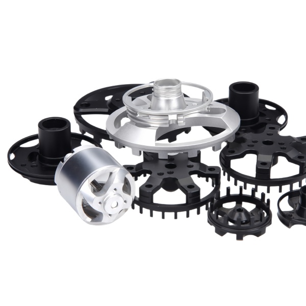
The hub-sprocket interface is a torque path that crosses three materials: aluminum, steel fastener, polymer
An aluminum motor hub carrying a black polymer sprocket or gear transmits the motor’s torque through a joint with three different materials, each with its own stiffness, thermal expansion, and creep behavior. The torque path: motor shaft → aluminum hub (via key or press) → fastener clamp → polymer sprocket → chain/belt. Each interface in that chain must be engineered, because the weakest one is where drive failures happen.
The critical interface is the hub-to-sprocket clamp. A polymer sprocket clamped between the hub’s flange and a retaining ring (bolted through) carries torque by friction between those faces and through the fasteners’ shear if the design has pins or keys. Polymer’s modulus (~3 GPa, versus aluminum’s 69 GPa) means the polymer’s clamp zone compresses under bolt load far more than metal would: bolt preload established at 20 °C relaxes as the polymer creeps under the compressive load, typically losing 20–40 % of preload within the first weeks of service. We therefore design this joint with a mechanical torque carrier—a key, pins, or the sprocket’s molded teeth engaging machined pockets in the hub—so friction is never the sole torque path, and we specify bolt re-torque after the first 100 hours of service as a standing note on the assembly sheet.
Sprocket tooth geometry in polymer demands molded-accurate pockets and a defined backlash
When the polymer sprocket is a customer-molded part mounted to our machined hub, the hub’s mounting features must match the molding’s real geometry, not its nominal CAD. Polymer moldings shrink 1–2 % out of the tool, and the shrink is not uniform across the part (the pocket pattern on a disc, for example, shrinks toward the disc center).
Our process: measure the customer’s sample sprockets’ pocket pattern and bore on a CMM, then machine the hub’s pins/pockets to the measured pattern with a centering adjustment (the molded pockets on a 200 mm sprocket may sit 0.5–1.0 mm closer to the axis than nominal). The alternative—machining to nominal and forcing the fit—stresses the polymer, mispositions the tooth pattern (the sprocket runs eccentric relative to the hub’s machining), and destroys the drive’s backlash consistency around the revolution.
Hub concentricity to the motor’s mounting pilot is the drive’s runout budget
The aluminum hub’s runout contribution adds directly to the sprocket’s tooth runout, which the chain or belt feels as tension variation at tooth-meshing frequency. On a belt drive, a 0.1 mm tooth runout at 100 mm radius produces cyclic tension variation on the order of the belt’s static tension—a noise source, a bearing-load source, and a belt-life reducer.
We machine hubs with all functional surfaces in one setup: motor pilot bore (or shaft bore), sprocket pilot, clamp face, and bolt-circle all cut from one datum grip. Hub total runout (bore to sprocket pilot) is held at 0.02 mm TIR. When the sprocket is press-fitted onto its pilot at our bench, we then verify the assembly’s tooth runout on an arbor: the molded sprocket’s own eccentricity (typically 0.05–0.15 mm for a good molding) adds to the hub’s 0.02, and the combined number is what the customer’s drive sees. If a molding arrives with 0.25 mm eccentricity, we ream its bore true (where wall allows) or reject it—the hub cannot hide the sprocket’s errors, only add its own.
Thermal management at the hub: motor heat flows into the polymer
The motor’s heat conducts along the shaft into the hub, and the hub’s flange—the sprocket’s mounting face—is one of the paths that heat takes. A polymer sprocket bolted to a 70 °C hub face loses strength (nylon loses half its modulus by 100 °C; glass-filled nylons and PEEK hold better), and its bolt-preload relaxation accelerates with temperature.
We design a thermal break into the hub for hot-running motors: the sprocket-mounting flange connects to the hub’s bore section through a reduced cross-section (a necked profile that carries the torque but throttles conduction), which keeps the flange 15–25 °C cooler than the bore section. The thermal break costs one machining pass and turns a marginal polymer joint into a stable one.
How we verify hub-and-sprocket assemblies before shipping
- Hub: Bore (H7 or per drawing, gauge-checked), pilot concentricity to bore (0.02 mm TIR on arbor), face runout (0.02 mm), bolt-circle position (CMM first article).
- Sprocket (if we mount it): Measured pocket pattern and bore before mounting; tooth runout of the full assembly on an arbor (molding eccentricity + hub contribution, recorded per assembly).
- Torque test (sample): One assembly per batch torqued to the drive’s rated torque with reversal, on a test fixture: no slip at the hub-sprocket interface (mark-and-verify method—prussian blue witness marks show any relative motion), fastener torque re-checked after test.
- Creep verification (design level): New designs get a 100-hour room-temperature plus 24-hour elevated-temperature soak at full clamp torque, with bolt preload measured before and after: preload retention must exceed 60 %. Designs failing this get the mechanical torque carrier (pins/keys) added before production.
This part belongs to our CNC Machining Parts range. The cnc machining parts pages collect the process notes, common materials and inspection points behind every product in the family.
Bonding the polymer gear to the aluminum hub
A motor hub with a polymer sprocket gear joins two materials that do not naturally stick, so the joint is either bonded, pressed, or molded in place, and each has a failure mode. A bonded gear depends on surface prep and adhesive cure; a pressed gear depends on interference the aluminum survives; a molded gear depends on the mold and the insert placement. We pick the join from the torque and the environment and we verify it with a pull or a torque-to-failure sample, because a gear that lets go of the hub is a silent failure that shows up as a stripped drive, not a clean break.
Wear at the sprocket tooth root
The sprocket teeth carry the load at their roots, and that is where a polymer gear wears or cracks first, so the root radius and the tooth shape are set by the transmitted torque, not by a standard tooth that looked close. We size the teeth with a margin for the start-stop shock a wiper or lift sees, and we choose the polymer for the tooth strength at the operating temperature, because a gear that is fine at room temperature can shed teeth when the hub warms. The tooth is a structural feature, not a convenience cut.
Specifications
| Item | Aluminum Motor Hub with Black Polymer Sprocket Gears |
|---|---|
| Brand | AUNOV |
| Designing | Send us your 2D drawing, or mail a sample for measurement, a manufacturability review comes back with the quotation. |
| Tooling | Every die designed and built in our toolroom, held and maintained under your part number. |
| Samples | First-article samples ship with a full dimensional report and material certification. |
| Materials | Aluminium leads the stock list for this part, alongside carbon steel (SPCC / DC01), 304 / 316 stainless steel, brass and copper, with grade selection confirmed at drawing review. |
| Surface finish | Plating, e-coat, powder coating, anodising or passivation as the drawing calls out, as called out on your print. |
| Processing | Progressive deep draw stages with in-line annealing as the draw ratio demands, then pierced and CNC-machined in house. |
| Equipment | Our press floor runs 5-250 T mechanical and 250-500 T hydraulic presses, CNC turning centres, climate-controlled CMM room. |
| Tolerance | +/-0.1 mm as-drawn, +/-0.03 mm on machined surfaces. |
| Delivery terms | FOB standard, DDP offered for EU and US, T/T or L/C, with D/P for repeat business, call-off schedules and blanket orders supported. |
Related Products


Request a Quote for This Part
Send a drawing or sketch — get material advice, tooling cost and a per-piece price within 24 hours (working days).