
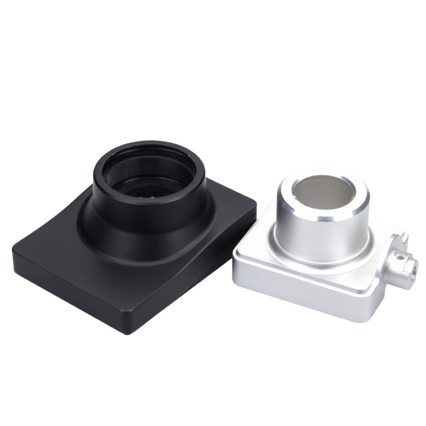
An anodised aluminium part with turned features looks like a straightforward combination, and it is one of the few manufacturing routes where two processes each add a tolerance, one of them grows the part, and both of them change how the surface behaves in ways that matter functionally. The anodising in particular is not a finish on this part – it changes the hardness, it changes the dimensional scheme, and it changes the friction and the thermal behaviour at every contact surface.
Turn-mill machining with critical diameters finished in one setup is the right route here. The interesting content is everything that happens after the machining.
What anodising actually does to an aluminium part
Four effects, and each one turns into a specification requirement.
- It grows the part. The oxide forms outward and consumes metal inward, so every external dimension increases and every internal dimension decreases. The amount depends on the class, and it is a range rather than a value. On a bore that receives a shaft, this closes the fit. On a length that sets a stack, it adds thickness. On an interference fit, it makes the interference larger and can crush a thin component.
- It hardens the surface. A hard anodise produces a genuinely hard, wear-resistant surface – harder than the substrate in some cases. That is useful on a wear surface and a problem on a bearing or sliding surface, where a harder, rougher counterface will wear the mating part faster.
- It thermally insulates. Aluminium conducts heat extremely well; the oxide does not. On any part where heat has to move across an anodised face, the interface becomes the thermal bottleneck rather than the metal. This is the single most overlooked consequence of anodising on a part that also has a thermal function.
- It changes the surface finish. The anodised surface is textured at a microscopic level, which improves adhesion for bonded joints and paint, and which also means a sliding contact has a different friction and wear behaviour than machined aluminium.
All four are consequences of the same process, and all four are avoidable by design if they are anticipated. None of them are avoidable by inspection after the fact.
Masking, which is the real specification
Since anodising changes dimensions and properties everywhere it goes, the useful question is not “where does the anodise go” but “where must it not go”. A short, complete masking list is worth more than a long paragraph about surface finish.
The faces that commonly need masking or an explicit allowance:
- Bearing and journal surfaces, where the anodised surface would change the fit and the wear partner.
- Threads – a coated thread changes both the fit and the corrosion behaviour, and the coating will crack or wear at the thread roots.
- Mating faces and registers that locate another component, unless the joint is designed with the anodised surface in mind.
- Heat-transfer faces – masked, or a thermal interface material is specified to bridge the oxide.
- Press or interference-fit surfaces, where the growth and the roughness both change the interference.
- Sealing faces for elastomers, where the hardness and the texture matter.
- Ground or precision dimension features, where the coating is a meaningful fraction of the tolerance band – this one is arithmetic rather than judgement, and it should be checked dimension by dimension.
- Any surface that will be welded, since the oxide is an excellent insulator and it has to be removed for a sound weld.
- Datum features and marking areas, and any surface that will be measured after finishing with a contact instrument, since a coating on a contact surface makes a measurement of the underlying metal ambiguous.
The best practice on a turned part with a mix of anodised and bare surfaces is to state the mask list by location – “mask the bearing diameter, the thread, and the flange face at the mounting end” – and to state whether the masked areas are left as machined, are chemically converted, or are plated afterwards. Those are three different surface conditions and the choice affects the fit, the corrosion behaviour and the appearance.
Grades and colour, on a functional part
The alloys on this route – carbon steel, 304 and 316 stainless steel, aluminium and brass – are held as standard stock. On this part the aluminium grade is chosen partly by the anodise class and partly by the colour, and this deserves stating because it is not always appreciated.
- 6061 is the general choice, and it takes a decorative anodise with a slightly deeper, slightly different tone than the pure alloys.
- 6063 has a lower silicon and iron content, takes colour more consistently between batches and between operators, and is the standard choice where appearance is a real requirement.
- 5052 is the structural choice where the part carries load, and its anodise is slightly different in tone again.
- 1050and 3003 give the cleanest, most consistent colour because they have almost no alloying elements to disturb the dye bath, and they are the right answer for a part whose main requirement is appearance.
So “aluminium, anodised black” is not a complete specification. “Aluminium 6063, class II anodising, dyed black to a retained reference, masked on the bearing diameter and the thread” is. The grade is a colour specification as much as a mechanical one.
Where the anodise is functional rather than decorative – a hard anodise on a wear surface, or a heavy coating for corrosion in a marine environment – the class and the thickness matter and the dimensional allowances have to be built into the drawing rather than discovered. Surface treatment matched to the duty, inspected with the dimensional report on the first article, is the right discipline; the specific thing that has to be added is the post-finish dimension scheme.
A re-chucked part carries anodise growth with a changed relationship
Critical diameters finished in one setup matters more on this part than the phrase suggests, because the anodise grows everything uniformly relative to the part’s geometry. If the part has been re-chucked, the features’ relationship to one another carries the setup error – and the anodise then makes every feature a consistent but incorrect distance from the axis. On a small aluminium part the growth is small, but the setup error is not, and the two compound.
Three practical notes on the route:
- Sequence the anodise last. Any machining after the anodise – a tap, a ream, a deburr – will cut through the coating and expose bright metal in a functional surface. That is why the masking list has to be settled before the part goes to the anodising line.
- Deburr before, not after. An anodised edge is a harder edge and it will chip differently. Sharp burrs on a part going into an anodise bath can become raised inclusions in the coating that are impossible to remove afterwards.
- Keep the design anodise-friendly. Sharp internal corners trap solution and dry out, leaving a visible or a functional defect. Generous radii in concave areas cost nothing at the machining stage and are almost impossible to add afterwards.
Tolerance, allocated around the coating
+/-0.01 mm on critical bores, confirmed at the DFM stage, with GD&T per the drawing and PPAP-style reports on request. On an anodised turned part the useful discipline is to identify which dimensions are functionally affected and handle them explicitly.
- Post-finish diameters and lengths, wherever the coating’s growth affects a fit or a stack. State them post-finish and give the coating class so the shop knows the allowance.
- Uncoated dimensions, at the tight end, with the coating explicitly excluded.
- True position and concentricity, unaffected by a uniform coating growth but very much affected by the setup, so this is where the one-setup rule pays.
- Bore size, as post-anodise where a shaft enters it, or pre-anodise with an explicit allowance, and the two are not interchangeable.
- General features at a general band, with the coating’s uniformity on a simple turned part being good enough that a general band remains achievable.
The general principle worth carrying away: on a coated part, every tolerance needs to say whether it is before or after the finish. That sentence costs nothing and it eliminates the most common source of dispute on coated components – a part that measures correctly before the finish and not after it.
Inspecting a coated part before the finish is how tolerances leak
- Dimensional inspection after the finish, not before. This is the single most important item on this page. On a coated part, inspecting before the finish and shipping on those results is the mechanism by which uncoated tolerances leak into a finished-part specification.
- Coating thickness, with the location stated, since a turned part with a shoulder and a bore will vary.
- Adhesion, on the first article.
- Masked areas verified, by inspection rather than by assumption. A part with four masked features should have all four checked, and a part where a masked area was missed will show it on the dimension check as well.
- Colour against the retained reference where appearance is a requirement, with the light source stated.
- Seal quality where a decorative anodise is used, since an inadequately sealed part will pick up handling oils and change in appearance.
- CMM data on the critical dimensions, with the dimensional report and the finish condition both travelling with the part number, and every stage logged.
Which surfaces actually touch something
Which surfaces on this part are actually in contact with something else, and which are simply visible? Every anodised surface that mates with something else is a place where the coating’s thickness, hardness, texture and thermal insulation are all in play, and every anodised surface that is purely visible is a place where none of that matters and only the colour does. Most anodised turned parts are a mixture of both, and the drawing normally treats them identically. Separating the two groups at the drawing review – and writing a masking list for the first group – is a fifteen-minute exercise that removes a set of dimensional allowances, several inspection items, and a recurring source of fit complaints. It is also the difference between a part that is anodised and a part that is designed to be anodised.
This part belongs to our CNC Machining Parts range. The cnc machining parts pages collect the process notes, common materials and inspection points behind every product in the family.
Specifications
| Item | Anodized Aluminum CNC Machined Parts |
|---|---|
| Brand | AUNOV |
| Designing | Quotation follows the print, not a catalogue – a manufacturability review comes back with the quotation; the agreed version governs every later batch. |
| Tooling | Tooling is designed and built in house and held under your part number, so the die stays dedicated to your part. |
| Samples | Approval is in writing, and the signed sample is kept as the reference for repeats. |
| Materials | Standard stock: carbon steel (SPCC / DC01), 304 / 316 stainless steel, aluminium, brass; mill certificates and heat numbers accompany the first article. |
| Surface finish | Surface treatment matched to the duty: plating, coating or polishing; the finish is inspected with the dimensional report on the first article. |
| Processing | Turn-mill machining, critical diameters finished in one setup; every stage is logged against your part number. |
| Equipment | Turning centres fed from bar, with machining centres for milled features, backed by CNC turning centres and a climate-controlled inspection room. |
| Tolerance | +/-0.01 mm on critical bores, confirms at DFM stage; GD&T per drawing, PPAP-style reports on request. |
| Delivery terms | FOB, CIF or DDP per Incoterms 2020, payment by T/T or L/C, quoted in USD or EUR; call-off schedules are supported. |
Related Products


Request a Quote for This Part
Send a drawing or sketch — get material advice, tooling cost and a per-piece price within 24 hours (working days).