
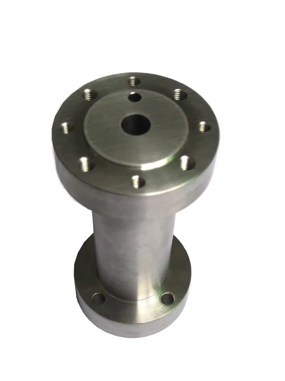
A turned part that is both knurled and anodised has two features that each independently add a dimensional tolerance, and the combination is where the surprises live. The knurl displaces material outward and cuts a pattern into the surface. The anodise grows an oxide layer outward and into that pattern. The result is a part whose as-delivered dimensions are determined by three operations in sequence, and each of them has a range rather than a value.
So this page is really about one question: when the drawing says a diameter, what does it mean, and whose hands does the answer pass through on the way there.
Knurl first, then anodise, and why the order matters
The sequence on this part is not arbitrary, and getting it wrong produces a knurl that cannot be seen or a surface that cannot be anodised.
- Knurling before anodising gives a pattern with sharp, well-defined teeth that gets cleanly coloured, and the oxide grows evenly over the tooth pattern. This is the normal and correct order for an appearance knurl. The downside is that the anodise softens the visual contrast slightly and fills the tooth valleys, so a fine knurl can become shallower in appearance than it is in fact.
- Anodising before knurling is done when the knurl is a working feature rather than an appearance feature – a grip surface, or a surface that needs to resist wear – and the part must be hard or already finished. It is uncommon, and it has a real problem: knurling an anodised surface tends to tear or burnish the oxide rather than cut it, and the result is a smeared, inconsistent surface rather than a crisp knurl.
Where both are wanted for appearance and grip – the usual case – the order is knurl then anodise, and the specification needs to say so, because the shop will otherwise have to guess and the two processes are not interchangeable.
What knurling does to the dimension
Knurling is a forming operation. Material is displaced, not removed, so the part grows. Three consequences on a turned part:
- The OD grows by approximately the knurl depth. A knurl specified at 0.3 mm depth makes the finished OD roughly 0.3 mm larger than the pre-knurl diameter, because the teeth stand above the root circle by the full depth.
- The knurl depth is conventionally specified from the root to the tip, which means the nominal diameter that the drawing calls out is the root diameter and the tip is nominal plus depth. Both should be on the drawing, because only the root is a stable dimension and the tip is what the user’s hand feels.
- The bore closes slightly. On a thin-walled part the inward displacement is real and it reduces the bore. On a thin-walled turned part this is the feature most likely to eat the wall needed for stiffness.
So the drawing needs, at minimum: the pre-knurl diameter, the knurl depth and pitch, the pattern type, and the post-anodise condition. Skipping the first is the classic omission, and it means the knurl depth has nowhere to be measured from.
What anodising does to the dimension
As covered on the enclosure pages elsewhere in this section, anodising converts aluminium at the surface into oxide, growing outward and consuming metal inward. The dimensional result on a turned part is a predictable but real growth, and it is not uniform around the part.
- On the knurled surface, the oxide grows over the whole pattern, so the tip dimension grows by approximately the coating thickness and the valleys grow by a similar amount but appear shallower.
- On a flat or turned surface, the growth is more even, but on a complex part the current distribution is not uniform and thicker sections and recessed areas take more oxide.
- On a hole, the coating closes it. On a bore that receives a shaft, this must be accounted for: a bore coated to 20 microns is about 40 microns smaller in diameter, which on a close-running bore is a real interference.
- On a bearing or locating surface, it is worse than that, because the anodised surface is harder and rougher than the machined surface and its sliding behaviour is different.
The sentence that resolves all of this is the same one: state whether dimensions are before or after finishing, and give the coating class and thickness range. A drawing that omits it on a knurled and anodised part is omitting the majority of the dimensional uncertainty.
Anodising a knurl, and the visual effect
There is an aesthetic dimension to this combination that is worth understanding, because customers often specify a knurl and then judge the result against an expectation they do not state.
- On a plain turned part, anodising produces an even colour with a clear specular highlight. It looks like a machined and finished part.
- On a knurled part, the highlight breaks up. Each tooth acts as a tiny facet reflecting at a slightly different angle, and the surface reads as a textured metal rather than a smooth one. This is a real and pleasing effect and it is why knurled and anodised parts are so common on instrument and control hardware – but it means an approved sample is essential, because a customer comparing a knurled anodised part against a plain anodised part will see a difference in colour that is purely optical and is not a colour mismatch.
- Colour in the valleys tends to be slightly deeper because the dye sits longer in the recesses. On a coarse knurl this is visible and on a fine knurl it is not.
- Hard anodising on a knurl is a genuine problem. A heavy oxide on a knurled surface fills the pattern substantially, and the knurl can end up visually and tactilely much shallower than specified. Where hard anodising and a knurl are both required, the knurl needs to be deeper and the pattern coarser than a cosmetic knurl would be, and this should be established before production rather than discovered on the first article.
Rolls, knurl types and the functional choices
The knurl specification has to be complete enough to be reproducible. Six items, and each of them changes the result:
- Pattern: diamond or straight. Diamond is two-directional and self-cleaning; straight is single-direction and cuts more aggressively. They are not interchangeable.
- Pitch, stated with a tolerance. A knurl 20 percent coarser than intended feels different and on a grip feature that difference is measurable by a user.
- Depth, stated with the measurement convention – root to tip is the usual one, and stating it removes the most common ambiguity on knurled drawings.
- Axial extent – full length, a band, or bands. A knurl that runs to the end of the part leaves no plain land, which matters if the part has to be chucked, gauged, or seated on a shoulder.
- Whether the knurl runs over any shoulder, step, or thread. A knurl that runs over a step destroys the step as a stop. A knurl that runs over a thread destroys the thread.
- Edge break on the knurl, stated. Sharp knurl edges damage gloves, damage anything slid over them, and are a hazard on a handheld part.
On a turned part specifically, one more: the knurl’s lead-in. A knurling tool has to enter the surface, and its entry leaves a visible start mark unless a lead-in ramp is machined. On an appearance part, specify a lead-in or specify where the knurl starts. On a functional grip, a lead-in is unnecessary and costs cycle time.
Material, and the 0.5to 3.0 mm range
Carbon steel, 304 and 316 stainless steel, aluminium and brass are all held. On this route, with knurling and a coating both in play, the material matters more than usual.
- Aluminium is the usual choice for an anodised knurled part, and the alloy choice follows the colour: 6061 and 6063 for decorative colour, 6063 preferred for the cleanest decorative result, 5052 where a structural alloy is needed and the colour is secondary. All of them knurl well.
- Brass knurls beautifully and is the right choice where a grip is needed without a coating, or where the part will be machined further after knurling. Brass knurls cleanly because it cuts rather than smears.
- Carbon steel knurls well and is the right choice for a wear application, but it will corrode, so it needs a plating or a coating, and the coating has the same dimensional consequences.
- Stainless Steel knurls but work-hardens aggressively, and a knurl that is interrupted leaves a smeared rather than cut pattern. It is the hardest of the four to knurl well and it is chosen for corrosion, not for the knurl.
The 0.5 to 3.0 mm stock range here means these are thin-walled turned parts, which brings the knurl’s effect on the wall back into focus. On a 0.8 mm wall with a 0.25 mm knurl, a third of the wall has been displaced. That is a legitimate part, but the knurl depth, the wall thickness and the anodise thickness need to be reviewed together rather than separately.
Tolerance, and what actually needs holding
+/-0.02 mm general machining with tighter bands on flagged dimensions, and capability checked on the first article before the run continues. On this part the flagged dimensions are specific:
- Bore diameter, stated post-finish, if a shaft enters it. This is the dimension most affected by the combination of knurl displacement and coating growth.
- Overall length or height, stated post-finish, if the part is a spacer or a standoff where the length matters and the coating is on the end face.
- Knurl root diameter and tip diameter, as separate values with their own bands, because neither one alone describes the knurl.
- Any bearing or locating diameter, which should be masked from coating or specified post-coating with an allowance for the coating’s hardness and roughness.
- Position and concentricity of the knurl band to the part’s axis, on a part where the knurl is a locating feature rather than a grip.
- General diameters and lengths at the general band. On a knurled part these do very little.
Batch records, and why this part needs them
Batch records filed so a repeat order starts from approved data is worth more on this part than on most, for two reasons. First, an anodised colour is a batch-consistent characteristic and never an absolute one, so the approved data is what makes a repeat order look like the first one. Second, a knurl’s appearance depends on the tool’s condition and on the setup, so a knurl that was approved at first article needs to be able to be reproduced. Between the two of them, an anodised knurled part is one of the hardest things on this site to repeat visually without a record, and one of the easiest with one.
A knurl check can pass while the diameter check fails, so measure both
- Knurl depth and pitch, on a first article and periodically, using a knurl gauge or optical comparison against a master, always measured on the same basis.
- Both the root and the tip diameters measured. A part can pass a knurl check and fail the diameter check, and only the pair tells you whether the knurl is right.
- Coating thickness and adhesion, with the measurement location stated, and the masked areas verified.
- Colour against a retained reference, with the light source stated. On a knurled surface the visual comparison has to account for the highlight effect, so an instrument reading where a band is specified is worth having.
- Wall thickness at the knurl, on a thin-walled part, as a specific inspection item rather than a nominal.
- CMM data on the flagged dimensions, with the dimensional report and the coating condition both travelling with the part number.
Grip, locator, or finish
Is the knurl a grip, a locator, or a finish? The three lead to different knurl depths and different tolerances, and the answer decides whether the knurl is a specification with microns in it or a general callout. A grip knurl for a hand-operated control wants to be coarse and positive, and the tolerance on its depth can be generous because what matters is that it feels right. A locating knurl has to be dimensionally controlled because it is doing a job, and its depth and its pattern become a fit. A finish knurl on an instrument knob is mostly about appearance and the tolerance can be almost entirely in the appearance dimension. Saying which of the three it is turns an ambiguous knurl callout into a real specification, and it also tells the shop whether the anodise is there for corrosion and colour or for wear resistance – which changes the coating class, the cost, and the risk of the knurl filling in.
Our CNC Machining Parts range is where this part sits. The cnc machining parts pages carry the process notes, common materials and inspection points behind every product in the family.
Specifications
| Item | Aluminum CNC Turned Knurled and Anodized Parts |
|---|---|
| Brand | AUNOV |
| Designing | The quotation follows your print, not a catalogue – unusual walls, threads or tolerances are checked for feasibility first. |
| Tooling | Tooling is built and held under your part number, so the die charge appears as its own quotation line, and the charge is refundable against agreed volumes. |
| Samples | First-article samples ship with a dimensional report and material certificate, so any deviation is corrected at sample stage, and later batches are gauged back to the signed sample. |
| Materials | Carbon steel, 304 / 316 stainless steel, aluminium and brass are all held in stock; mill certificates and heat numbers accompany the first article. |
| Surface finish | Natural, plated or coated – the print decides, and the agreed finish is logged; finish thickness and adhesion checked on the first article. |
| Processing | Turn-mill machining, critical diameters finished in one setup; batch records are filed so a repeat order starts from approved data. |
| Equipment | Turning centres fed from bar, with machining centres for milled features; first articles and batch samples are checked on the CMM. |
| Tolerance | +/-0.02 mm general machining, tighter on flagged dimensions; capability is checked on the first article before the run continues. |
| Delivery terms | Shipping terms are set with the order: FOB, CIF or DDP, T/T or L/C, door delivery quoted. |
Related Products


Request a Quote for This Part
Send a drawing or sketch — get material advice, tooling cost and a per-piece price within 24 hours (working days).