
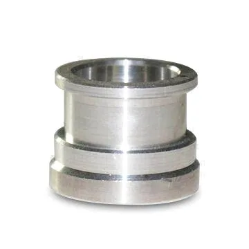
A hose barb threaded adapter is a part whose entire function is to be gripped by something soft. Everything about it is therefore about the relationship between a hard machined surface and a soft hose, and the requirement that is most often missed is that the barb’s dimensions are meaningless on their own – they are a pair with the hose’s inside diameter and wall thickness.
This is the same insight as the compression fitting and the flare fitting, and it is worth stating in exactly the same way: the fitting should be specified with the hose, not with a size.
The barb’s geometry, which is a gripping profile
A barb is a series of ridges that the hose is pushed over, and the hose deforms around them. Three features, and each one works.
- The pitch. The distance between the ridges. A coarse pitch grips well and is easy to push on; a fine pitch grips less hard but is less likely to damage a thin-wall hose. The pitch is a design choice and it interacts with the hose’s reinforcement – a reinforced hose cannot be stretched over a fine pitch and a wire-reinforced hose needs a specific one.
- The height of each ridge. How far the ridge stands proud of the underlying body. This is what the hose’s inner surface latches onto, and it is the ridge’s height that determines the pull-out strength. On a thin-wall hose, a tall ridge will cut into the hose and can work through it.
- The angle of the ridge’s flank. The leading flank is what the hose slides over during assembly and the trailing flank is what it latches onto. A leading flank that is too steep will not let the hose on; a trailing flank that is too gentle will not hold.
So the barb’s geometry is a three-dimensional specification and it is the geometry of the gripping action, not of the fluid passage. And it has to be designed for a hose – a given barb geometry will work on a heavy three-layer suction hose and fail completely on a thin-wall fuel line, or the reverse.
The bore, which is the part nobody thinks about
The bore through the barb is a flow path and it interacts with the barb’s geometry in a way that is not obvious.
- The bore must be at least as large as the hose’s bore, or the fitting restricts the line. This is the most common dimensional error on a barb fitting, and it is easy to make because the barb’s OD is the visible dimension.
- Reducing the bore to improve the barb’s strength is a bad trade. A barb’s strength comes from the material around the bore, so thickening the barb’s root thickens the fitting and reduces the bore. Where a barb needs to be stronger – on a hose that will be pulled – the answer is a harder material or a longer engagement, not a smaller bore.
- The bore’s internal finish matters on a fuel or a hydraulic line where particulate in the fluid will come from the bore’s roughness, and it matters on any hygienic application.
- The internal radius where the bore meets the barb’s root – on many designs the bore is stepped and the step is at the barb’s root, which is a debris trap and a stress concentration in the hose. A radius there costs nothing.
Pull-out strength, which is the real requirement
A barb connection’s primary requirement is not pressure – it is that the hose stays on. And that requirement is a calculation involving four things, three of which are the hose’s properties.
- The barb’s engagement length in the hose. Longer engagement means more ridges in contact and therefore more holding. This is the fitting’s variable and it is a free one if the geometry allows.
- The hose’s inside diameter and wall thickness, which determine how far the hose has to stretch over the barb and how much material is available to grip.
- The hose’s material and its reinforcement. This is the biggest variable of all. A reinforced hose with a wire or a fabric plies will resist being stretched and will grip over a barb differently from an unreinforced rubber hose. A thin-wall unreinforced PVC or rubber line will grip much less and cannot be pushed over a coarse barb at all.
- The assembly conditions. A hose that is heated before being pushed on will grip better and can often use a coarser barb. A hose assembled cold onto a tight barb may be damaged. Where a design depends on assembly conditions, they have to be specified.
So the pull-out strength is not a number the fitting’s supplier can guarantee in isolation. It is a property of the fitting and the hose together, and the drawing should state the hose standard it is designed for – the outside diameter, the inside diameter, the wall thickness, the material, and whether it is reinforced. That is the specification, and it is absent on most barb fittings.
The thread, and the other half of the connection
The threaded end is the other connection, and on this part it has two specific consequences.
- Which seal method. A threaded hose barb adapter might seal on the thread – a tapered pipe thread – or it might carry a bonded seal or an O-ring at the thread, or it might use a parallel thread with the gasket elsewhere. The choice determines the torque range, and it determines whether the fitting can be remade after being removed. On a barb adapter that will be removed and replaced regularly, a parallel thread with an O-ring or a bonded seal is the better answer because a taper will be damaged.
- The thread’s plating and galling. On stainless steel, masked or passivated, and the same galling risk as on every stainless steel threaded part on this site. On a barb adapter the consequence is specific: a galling thread that has to be cut off damages the port it is in, and on a hydraulic or a pneumatic manifold port that is an expensive repair.
- The wrench flats, which are functional because a barb adapter will be tightened by hand or by wrench and the flats have to be a wrench fit rather than a general dimension.
The fitting and the hose have to be decided together
Materials held include carbon steel, 304 and 316 stainless steel, aluminium and brass, with grade and temper confirmed in writing before tooling. Four specific points, and the first is the important one.
- The fitting’s material and the hose’s material have to be compatible. This is the coupling that matters on this part, and it is not a standard galvanic question. A brass barb fitting on an aluminium hose, or a steel barb on a stainless steel hose, or a plastic hose on a metal barb – each combination has a specific behaviour, and the barb’s ridge height has to be chosen so it does not cut the hose.
- 316L is the normal stainless steel answer, on the chloride logic and the L grade where there is welding. And a stainless steel barb has a specific property: it work-hardens and it will slightly score the hose’s inner surface as it is pushed on, so on a soft hose a stainless steel barb needs its ridges to be broken or rounded.
- Brass is the traditional material and it is a good one for hoses: it is easy to machine to a fine barb profile, it is softer than steel so it is gentler on the hose, and it is corrosion-resistant. Its limitations are dezincification and its galling against steel.
- Carbon steel with a plating is the conventional choice on hydraulic lines, and the plating is the second requirement: a plated barb’s ridges will not be as sharp as a bare steel’s, and the plating changes the barb’s effective diameter, so the plating thickness is a functional dimension on this part rather than a finishing detail.
A coating on the barb changes the effective ridge height the hose sees
Finish selected from the drawing – plating, coating, anodising or passivation – with the finish inspected with the dimensional report on the first article. Two items specific to this part.
- The barb’s ridges, where a coating changes the effective ridge height and the grip. A plated barb grips less than a bare one of the same nominal geometry, and on a thin-wall hose that difference can be the difference between a connection that holds and one that does not. So the barb’s geometry should be specified in the finished condition, or the coating should be masked and the ridge’s dimensions taken from the machining.
- The threads, masked or specified post-finish with an allowance, and passivated rather than plated on stainless steel.
- On a barbed part, burrs are the defect that matters most. A burr on a barb’s ridge will damage the hose’s inner wall as it is pushed on, and it will do it in a way that is not visible until the hose fails. The ridges’ edges need to be broken – not polished, not deburred to nothing, just broken so that the transition onto the hose is smooth.
A barb’s major diameter at the valley root is an unusual scheme
+/-0.01 mm on ground diameters, dimensional reports accompanying the first article. On a barb adapter the flagged dimensions are the barb’s geometry and the thread, and the barb’s tolerance scheme is unusual.
- The barb’s major diameter at the root of the valleys, and the ridge’s height separately. Both matter, because the hose’s stretch is set by the root’s diameter and the grip is set by the ridge’s height.
- The barb’s pitch, where it is controlled, because the pitch and the hose’s reinforcement have to agree.
- The engagement length, which sets the pull-out strength and which is a general tolerance rather than a tight one – but it should be stated, because it is a functional dimension and a general band of unspecified length is not a specification.
- The bore’s diameter and its step position, and the bore’s internal finish.
- The thread class and pitch diameter, gauged, and the seal face’s flatness where there is one.
- The wrench flats as a fit.
Pull-off force is what a barb actually promises
- A functional pull test – push the specified hose onto a sample assembly and pull it off, measuring the force, or verifying that it holds a stated load. This is the test that tests the specification on this part, and it is the one that a dimensional inspection cannot replace.
- The barb’s root diameter and ridge height, measured on a first article and periodically.
- Visual inspection of the ridges’ edges for burrs, against an agreed standard.
- Thread gauging and sealing face inspection as normal.
- A pressure test on the assembled connection with the specified hose, because a barb connection that has passed a pull test can still leak at its bore.
- Finishing thickness and adhesion on the first article, with the masked threads and any masked barb verified, and the coating’s condition recorded because it changes the grip.
The hose standard, and whether it is pulled or pushed on
What is the hose – its inside diameter, its outside diameter, its wall thickness, its material, and whether it is reinforced – and is this connection going to be pulled on, or only pushed onto? Those answers decide almost everything on this page. A thin-wall unreinforced rubber line needs a gentler barb and a smaller engagement and will not accept a coarse profile; a wire-reinforced suction hose needs a specific pitch and needs the hose to be assembled warm. A hydraulic line that will be pulled – because it is on a boom, or it is being routed to a moving component, or it will be handled – needs a pull-out requirement stated as a load, and the fitting has to be designed against the hose’s actual strength rather than against the fitting’s own. And a connection that will be made and remade in the field has a different requirement again, because a barbed connection is not really a reusable connection – every push-on cycle wears the hose. Stating whether this is a permanent installation or a serviceable one decides whether the barb is the right component at all, or whether a compression or a crimped fitting, which is a genuinely reusable and verifiable connection, would be the better answer. One line of enquiry – the hose standard – is the difference between a barb fitting that works and one that gets returned.
CNC Machining Parts is the parent range for parts like this one; the overview page gathers the tooling logic, finishing options and tolerance notes that apply across the family.
Specifications
| Item | Stainless Steel Hose Barb Threaded Adapter |
|---|---|
| Brand | AUNOV |
| Designing | Quotation follows the print, not a catalogue – unusual walls, threads or tolerances are feasibility-checked first; the agreed version governs every later batch. |
| Tooling | Tooling is built and held under your part number, so a die can be re-cut against the approved drawing, and ownership is confirmed on the quotation. |
| Samples | Approval is in writing, and the signed sample is kept as the reference for repeats. |
| Materials | Materials held include carbon steel, 304 / 316 stainless steel, aluminium and brass; grade and temper are confirmed in writing before tooling. |
| Surface finish | Finish selected from the drawing: plating, coating, anodising or passivation; the finish is inspected with the dimensional report on the first article. |
| Processing | CNC turning from bar or billet, concentricity held across operations; in-process checks sit between stages, not only at the end. |
| Equipment | CNC turning centres with bar feeders and 3-/4-axis machining centres; first articles and batch samples are checked on the CMM. |
| Tolerance | +/-0.01 mm on ground diameters, with GD&T taken from your print; dimensional reports accompany the first article. |
| Delivery terms | FOB with DDP offered for EU and US addresses; payment T/T or L/C, freight quoted to destination. |
Related Products


Request a Quote for This Part
Send a drawing or sketch — get material advice, tooling cost and a per-piece price within 24 hours (working days).