
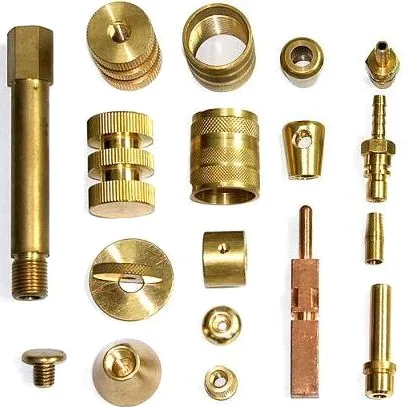
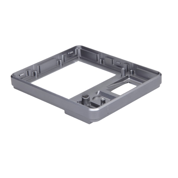
A machined aluminium enclosure is usually drawn as a box with a lid, a set of screw holes, and some ventilation, and it is usually designed as though those three things are the requirement. They are not. On a machined enclosure the requirement is almost always a flat, stiff, flat-faced joint that will take a screw, conduct heat, and hold an electromagnetic barrier – and all four of those are properties of the machining rather than of the shape.
The reason this part is harder than it looks is the material. Aluminium machines beautifully, which means it is easy to make a thin-walled box that looks right and behaves badly. Thin aluminium walls move with temperature, they deflect under the pressure of a fastener, and they bow during and after machining because the residual stress left by removing material from one side of a plate is not zero. On a deep-drawn box the forming process leaves the same problem, but the part has a long history of being made this way; on a machined enclosure it is often the first time anyone has looked at it.
The lid joint, which is the whole part
Almost everything that matters on this enclosure happens along the line where the lid meets the body. That line has to do four jobs at once, and each one constrains the others.
- It has to be a mechanical joint, so it has to take the loads without the lid working loose and without the fastener fretting in its hole.
- It has to be an electromagnetic barrier, if the enclosure is doing that job, and a bare aluminium joint between two machined faces will not be an RF-tight joint by itself. It needs either a conductive seal or a defined joint geometry.
- It has to be a thermal path, because the thing inside generates heat and the lid is usually where the heat has to leave.
- It has to be a visual line. On a finished product the joint is the most visible feature on the enclosure, and a joint that shows a step, a waviness, or a mismatch in finish between two anodised surfaces reads as a cheap product even when it is perfectly made.
Those four pull in different directions. A recessed, lapped, or spigoted joint hides the fastener and removes the step, which helps appearance and stiffness, and it adds a machined feature to an already complex part. A conductive gasket adds compliance, which helps RF and helps the joint survive thermal movement, and it adds a fourth interface whose compression has to be controlled. It is a genuinely constrained design problem rather than a drawing exercise.
Flatness, and the thing that kills it
The single most important dimension on this part is the flatness of the joint face, and the single most common reason it fails is heat generated during machining.
An aluminium plate that has had a large pocket machined out of one side has had stress removed from one side only. It will bow. The magnitude depends on how much material was removed, how far from the neutral axis, and how thick the remaining section is. It is predictable enough to compensate for, but only if the design expects it – which means the finished part may need to be stress-relieved, or the roughing strategy has to be sympathetic, or the flatness has to be achieved by a final facing operation on the whole face rather than by profiling the pocket edges.
Three practical points on this part specifically:
- Specify flatness over the joint face, and say what it is measured against. A flatness of 0.05 mm over a 120 mm face is a real number. A general parallelism to an unspecified datum is not, and on a large aluminium face the two can differ by an order of magnitude.
- State whether dimensions are before or after finishing. Anodising adds material. On an enclosure where the lid and the body both go into the same bath, the joint faces both grow by a similar amount and the joint stays consistent – but only if the growth is small relative to the joint’s tolerance. On a bolt-hole pattern, the growth is around the hole and it closes the clearance, which is fine for a clearance hole and a problem if the hole is a locating feature.
- Say whether the joint faces are masked during anodising. If the joint is a plain anodised joint, it is insulating on both sides, which is good for galvanic isolation and bad for RF continuity. If it needs to be conductive, masking and then a chemical conversion or a conductive finish on the masked area is the usual answer.
Wall thickness, which is the real compromise
Machined aluminium enclosures have a wall thickness that is set by the machining rather than by the forming, and that is a significant constraint. A deep draw can produce a 1 mm wall in a tall box almost as easily as a 2 mm wall. A machined enclosure has to have the outer and the inner surfaces both machined or formed, and on a box that means either a thin wall between two machined faces, or a wall that has to be thick enough to be rigid enough to be machined without chatter.
So the wall thickness on this part is a three-way compromise:
- Structural – the wall has to resist being pushed on, and a thin wall across a large unsupported span will bow under a hand or under a gasket.
- Thermal – if heat has to move through the wall, a thick aluminium wall is actually good, because aluminium’s volumetric thermal conductivity is high. But the path through the wall is rarely the bottleneck; the interfaces are.
- Manufacturing – a wall that is too thin will chatter, will not hold a flat face after machining, and will vary in thickness across the part, which means it varies in how it conducts and how it deflects.
A useful principle here: on an enclosure, aluminium is rarely the worst thermal material for the wall. The wall is nearly always the least important thermal resistance in the chain. The chain runs from the heat source across an interface, possibly through a thermal pad or isolator, into the enclosure wall, across another interface, into a heatsink or into air. Of those, the interfaces dominate. A machined enclosure designed around an insulating anodised mounting surface can have a very conductive wall and still dissipate poorly, and the fix is almost never to make the wall thicker.
Fasteners, bosses and thread design
The screw holes in a machined aluminium enclosure look like the simplest feature on the drawing and they are one of the most common sources of problems.
- Tapped holes versus clearance holes with a nut. A tapped hole in aluminium has almost no thread life and will strip. Where the fastener is removed more than a couple of times, the correct answer is a clearance hole and a nut, a rivnut, or a steel insert. Where the fastener stays, a tapped hole is fine and cheaper.
- Boss design around the hole. A hole in a thin wall has no bearing surface and the fastener will dimple it. A boss gives the material somewhere to push against. The boss needs to be thick enough that the fastener’s bearing stress does not exceed the aluminium’s yield, which is a calculation and not a judgement call, and it needs to be located so it does not sit in the path of water or in a place that will be seen.
- Hole spacing and edge distance. Two effects combine: an aluminium hole needs a larger edge distance than a steel hole because the material is softer, and the fastener’s own clamping will locally yield the aluminium if the bearing area is too small.
- Thread engagement. In aluminium, useful engagement is a multiple of the thread diameter, and underspecifying it is the usual cause of a stripped enclosure after two services.
There is a further reason to think carefully about where the holes go on this part, which is that the enclosure may be assembled and disassembled repeatedly in service. If it will be, then the mating faces need to be hard enough to take the fastener’s bearing repeatedly, and that pushes towards a steel insert, a stainless steel fastener with an appropriate washer area, or a larger boss, rather than towards a small screw in a thin aluminium wall.
Ventilation, and the holes nobody forgets to design
Every opening in an enclosure degrades whatever the enclosure was doing – whether that was shielding, ingress protection, or a pressure boundary. Vent holes are the standard way a machined enclosure admits dust, water and RF, and they are usually added late.
Things worth specifying:
- Hole size and pattern, with an open area figure if airflow matters. A pattern of small holes gives more open area for less leak-through than one large hole of the same area.
- Whether a membrane or filter is fitted, and if so, where it seats and how it is retained. A filter that sits on a flat machined face is straightforward; one that sits in a pocket needs a pocket that is not a dead end for water.
- Water shedding, on an outdoor enclosure. That means the openings face downward or are recessed, and it means the enclosure’s lowest point is a feature rather than an accident.
- Whether the hole’s edge is a burr risk, and the hole’s edge condition specified. On a deburred-then-anodised part the hole edge is where the anodising will look different and where a burr will be covered rather than removed.
Minimise handling and re-chucking across turning, milling and drilling
Turning, milling and drilling sequenced to minimise handling and re-chucking is the right instruction for this part, and the sequencing question is worth more than the machine list. A box like this has an inside and an outside, and machining the inside features while the outside is still on the machine means the outside face is finished last and therefore stays flat – which is exactly what a lid joint needs.
In-process checks between stages rather than only at the end are worth the small cost on this part, because the dominant failure mode is a slow drift in flatness as the tool wears, and the drift is invisible on any single part. It shows up as a batch that is all inside tolerance and a stack that will not close, which is a much more expensive symptom than an individual part out of tolerance.
Grinding is available for faces where the print demands +/-0.005 mm, and on this part the ground face would be the joint face or the mounting face. Grinding a large aluminium face is possible but it is not the first choice; a stable, well-supported milling operation with a defined finishing strategy will often hold a usable flatness more cheaply, and the place to decide is at the drawing review rather than after the first article.
Flatness across both joint faces decides whether the enclosure seals
- Flatness of both joint faces, reported as actual values over the actual face, because this is the characteristic that decides whether the product works.
- Flatness of the mounting face where the enclosure bolts to something.
- Position of the hole pattern to the joint face, as a separate characteristic from hole size, because it is the relationship that has to be right.
- Wall thickness, at the thinnest expected location, as an inspection item and not as a nominal.
- Thread condition on every tapped hole – this is an inspection item on a part that will be assembled in service, and a stripped or partially formed thread is a reject even though it measures correctly.
- Finishing thickness and adhesion, on the first article, with the masked areas verified.
Machined, or drawn or folded and welded
Does this enclosure need to be machined at all, or would a deep-drawn or folded-and-welded box with a small machined operation for the mounting features do the same job? On a shallow, thin-walled box with a flat lid, a drawn or folded body is usually cheaper, lighter, stiffer per unit of mass, and better looking than a machined one. Machining earns its place when the enclosure has deep pockets, complex three-dimensional features, thin walls combined with heavy ribs, tight tolerances across large distances, or a need for no joints at all in the body. Establishing which side of that line this part falls on is a fifteen-minute conversation and it can change the route, the cost and the lead time by a wide margin. It is worth having that conversation before the enclosure is drawn, and not after the first machining quote arrives.
This part belongs to our CNC Machining Parts range. The cnc machining parts pages collect the process notes, common materials and inspection points behind every product in the family.
Specifications
| Item | Aluminum CNC Machined Electronic Enclosure |
|---|---|
| Brand | AUNOV |
| Designing | Your drawing sets the part – unusual walls, threads or tolerances are feasibility-checked first; the agreed version governs every later batch. |
| Tooling | Progressive and drawing dies are designed and built in house, so the die charge appears as its own quotation line, and the die remains dedicated to your part. |
| Samples | Sample parts are measured and reported before submission, so the sample is retained as the master, and production starts only after your written sign-off. |
| Materials | 1050 / 3003 / 5052 / 6061 aluminium, 0.5-3.0 mm stock – temper matched to the forming depth or machining route of this enclosure. |
| Surface finish | Zinc, nickel or chrome plating, anodising, passivation or e-coat; alternatives quoted with the quotation, samples approved in writing. |
| Processing | Turning, milling and drilling sequenced to minimise handling and re-chucking; in-process checks sit between stages, not only at the end. |
| Equipment | CNC turning centres with bar feeders and 3-/4-axis machining centres, with CNC turning centres for secondary operations and CMM inspection. |
| Tolerance | +/-0.005 mm achievable on ground faces where the print demands it; capability is checked on the first article before the run continues. |
| Delivery terms | FOB Ningbo or Shanghai, payment by T/T or L/C, quoted in USD or EUR; sea or air freight is quoted to your door. |
Related Products


Request a Quote for This Part
Send a drawing or sketch — get material advice, tooling cost and a per-piece price within 24 hours (working days).